OCT Swept Laser with Cavity Length Compensation
a laser and cavity technology, applied in lasers, semiconductor lasers, instruments, etc., can solve the problems of device complexity, dispersion and instability, and its own performance problems, and achieve the effect of increasing coherence length and improving performan
- Summary
- Abstract
- Description
- Claims
- Application Information
AI Technical Summary
Benefits of technology
Problems solved by technology
Method used
Image

Examples
first embodiment
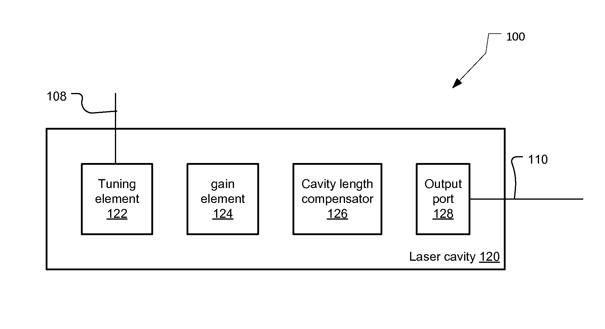
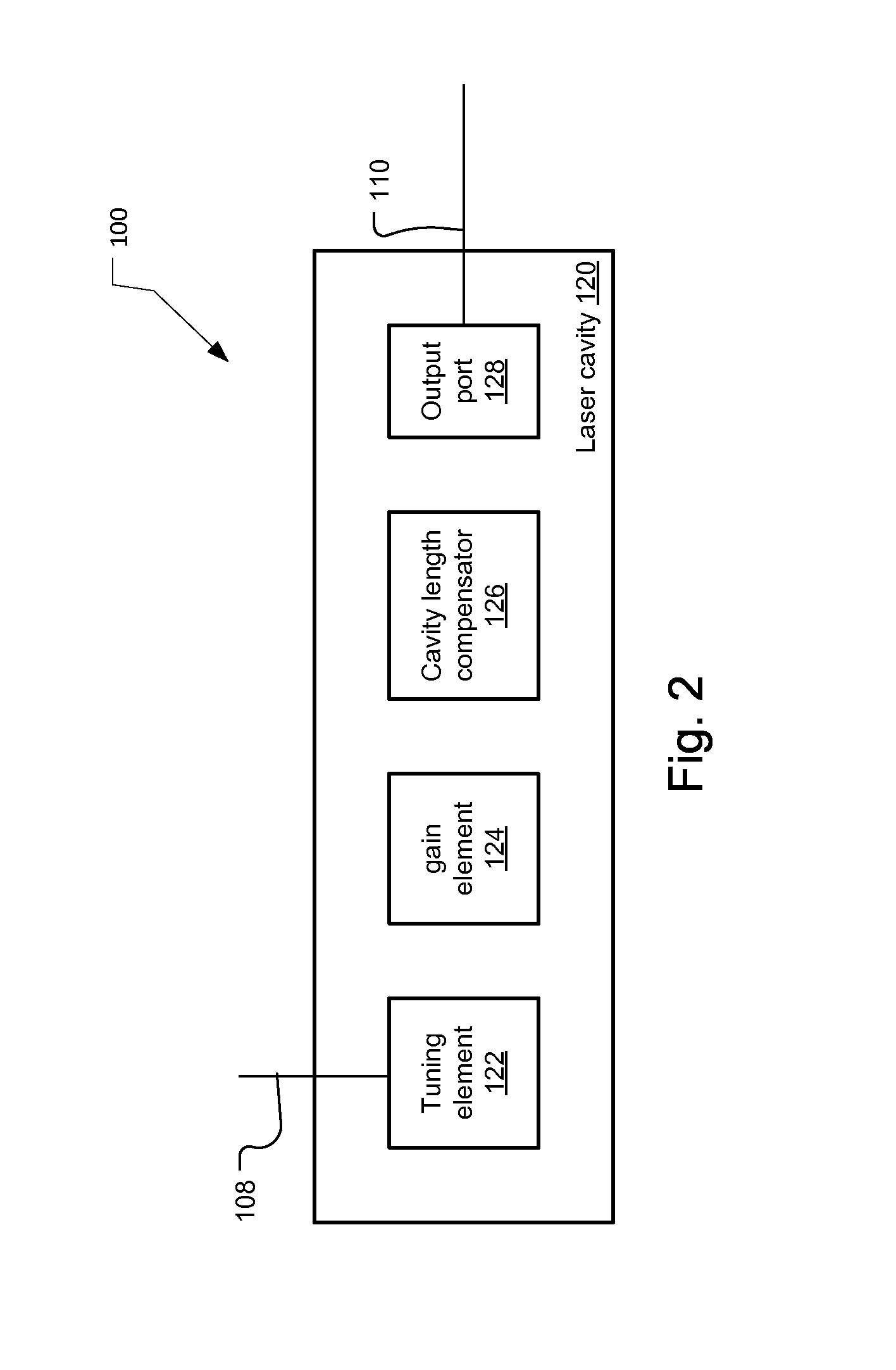
[0047]FIG. 3A illustrates the swept laser 100. In this example, the cavity length compensator 126 comprises two gratings 129, 130 and a mirror 132.
[0048]In more detail, the first grating 129 receives the light exiting from the gain element 124. It spatially disperses this light such that the longer wavelengths / lower frequencies travel a longer distance to a second grating 130. The pitch of the second grating is such that the different optical or frequencies or wavelengths impinging on the grating 130 along its length are reflected to be parallel to each other. The wavelengths then reflect off a mirror 126 to return to the second grating 130 and then are the combined by the first grating 129 to reenter the gain element 124.
[0049]In this way, the two gratings 129, 130 function to provide different effective optical cavity lengths for the different frequencies that may oscillate in the cavity 120. In one current example, the scanband extends over the wavelength range: 1250 to 1350 nm. ...
second embodiment
[0055]FIG. 6 shows a second embodiment that is similar to the embodiment of FIG. 3. It adds an additional cavity length compensating element 134, however. Specifically, a solid lens element is added that changes the optical length seen by the different frequencies of the swept optical signal oscillating in the cavity 120.
[0056]This correction plate compensating element 134 shortens the cavity length in the direction of the edges of the scanband relative to the center wavelength. In one example, it shortens the cavity by 600 wavelengths at 1250 nanometer and 1350 nanometers relative to the center wavelength of 1300 nanometers.
[0057]FIG. 7 shows the optical cavity length as a function of wavelength over a scan band stretching from 1250 to 1350 nm. Preferably, the relationship is linear in frequency. In the example, the compensator 126 increases the length of the cavity from about 19 millimeters for 1250 nm or about 25 millimeters for 1350 nanometers.
[0058]FIG. 8 is a plot of the mode ...
PUM
 Abstract
Description
Claims
Application Information
 - R&D
- Intellectual Property
- Life Sciences
- Materials
- Tech Scout
- Unparalleled Data Quality
- Higher Quality Content
- 60% Fewer Hallucinations
Browse by: Latest US Patents, China's latest patents, Technical Efficacy Thesaurus, Application Domain, Technology Topic, Popular Technical Reports.
© 2025 PatSnap. All rights reserved.Legal|Privacy policy|Modern Slavery Act Transparency Statement|Sitemap|About US| Contact US: help@patsnap.com