Ultrasonic Test Equipment and Evaluation Method Thereof

a technology of ultrasonic test equipment and test equipment, applied in the direction of instruments, specific gravity measurement, processing detected response signals, etc., can solve the problems of limited improvement in efficiency, inability to discuss an increase in scanning speed in general terms, and inability to detect defects without volum

Active Publication Date: 2014-08-21
KK TOSHIBA
View PDF5 Cites 22 Cited by
  • Summary
  • Abstract
  • Description
  • Claims
  • Application Information

AI Technical Summary

Benefits of technology

[0019]The present invention was made in consideration of the circumstances mentioned above, and an object thereof is to provide an ultrasonic test equipment and an evaluation method for evaluating the test result by using a low-frequency and a nonlinear ultrasonic wave to thereby detect a defect of an object to be tested in a wide positional range and obtain physical information such as length and depth of the defect.
[0020]The above and other objects can be achieved according to an embodiment of the present invention by providing an ultrasonic test equipment includes: a signal generating mechanism that generates a voltage waveform; an ultrasonic transmitting mechanism that excites ultrasonic vibrations having a lower frequency than a predetermined frequency to an object to be tested; an ultrasonic receiving mechanism that receives an ultrasonic response from the object to be tested; an AD converting mechanism that digitizes the received ultrasonic waveform; an analyzing mechanism that performs frequency analysis of the digital ultrasonic waveform digitized by the AD converting mechanism; and an evaluating mechanism that extracts a variation of a nonlinear ultrasonic component from a frequency component of the digital ultrasonic wave obtained by the frequency analysis, compares the variation with defect data information in a defect information database, identifies a physical quantity of defect information of the object to be tested, and evaluates a defect in the object to be tested; and a control mechanism that partly or entirely controls a measurement system.
[0021]According to another embodiment of the present invention, there is also provided a method for evaluating a test result by an ultrasonic test equipment, which includes the steps of: transmitting an ultrasonic wave having a low frequency lower than a predetermined frequency to an object to be tested; receiving an ultrasonic response from the object to be tested by an ultrasonic receiving m...

Problems solved by technology

The RT is effectively used for detecting a defect with a volume, such as a hole, that exists in a structural object, but not suitable for detecting a defect with no volume, such as a crack and a peel-off.
Since the RT includes testing steps such as exposure and development, the improvement in efficiency is limited.
It is thus difficult to discuss an increase in the scanning speed in general terms.
If the probe size is simply increased, its resolution is deteriorated, and thus, the increase in the probe to a larger size is not suitable for practical use in flaw detection of a structural object or the like.
However, the array probe has a larger volume, and thus, the handling thereof becomes difficult.
However, it becomes difficult to control a beam when the elements are spaced at a pitch more than half the wavelength.
It is thus not practical to i...

Method used


Image

  • Ultrasonic Test Equipment and Evaluation Method Thereof
  • Ultrasonic Test Equipment and Evaluation Method Thereof
  • Ultrasonic Test Equipment and Evaluation Method Thereof

Examples


first embodiment

Effect of First Embodiment

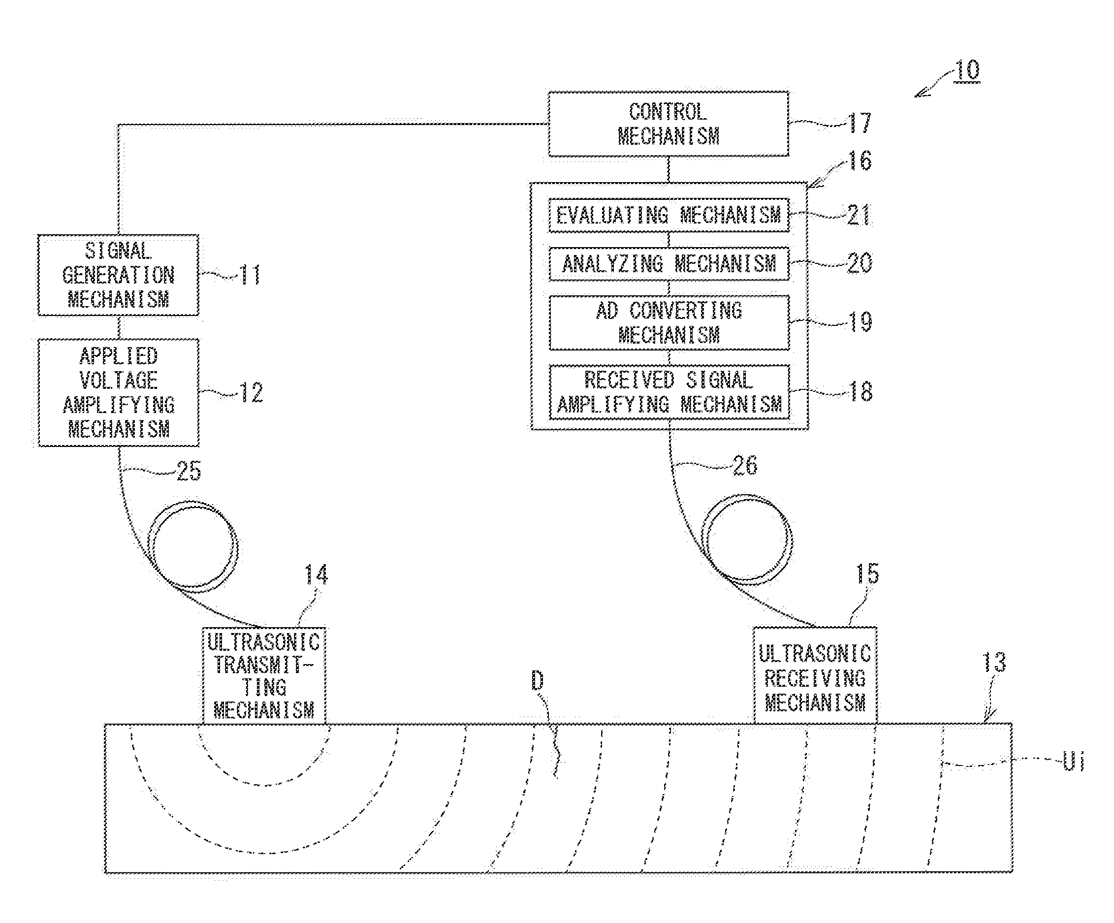
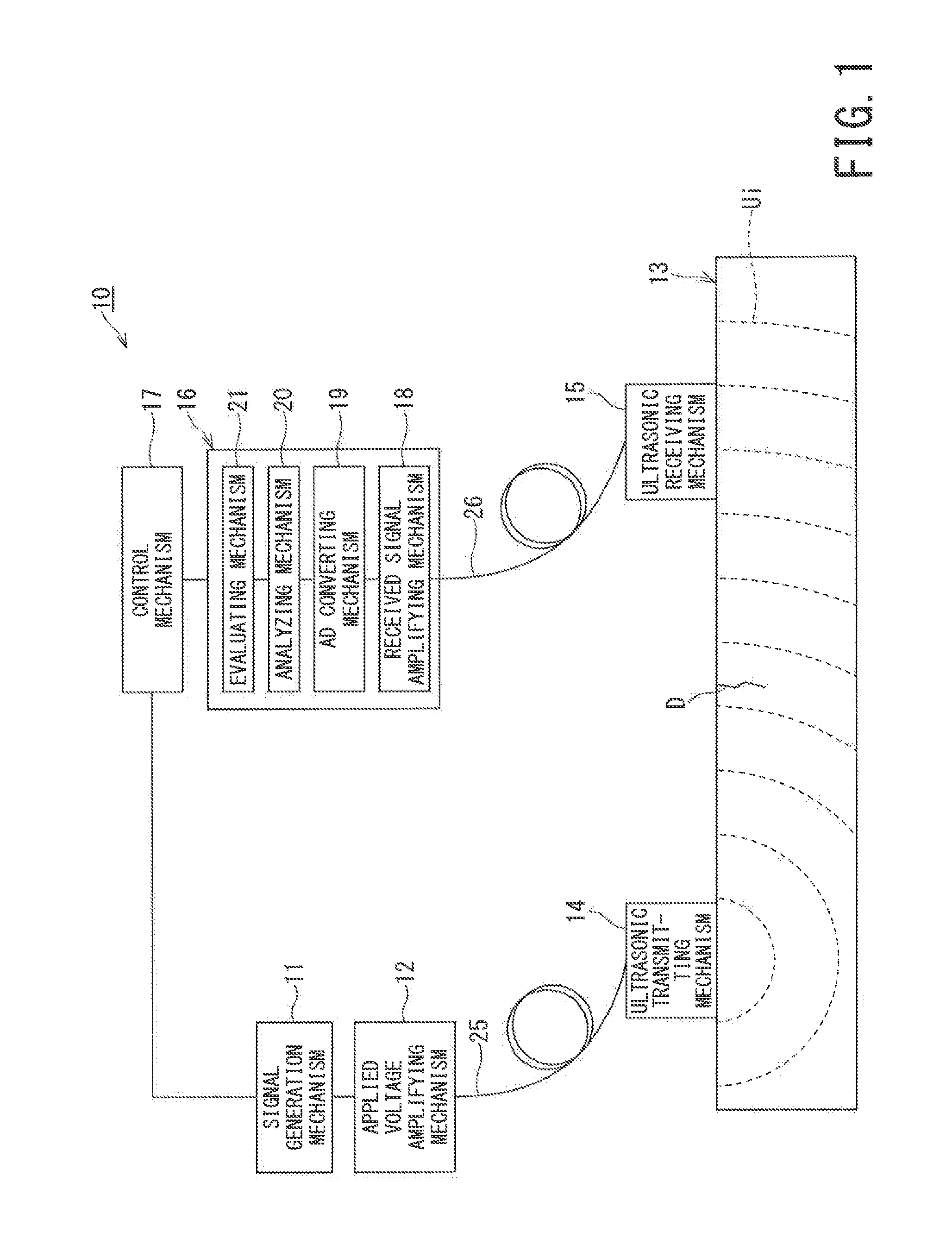
[0096]The defect information of the object to be tested 13 obtained in the evaluating mechanism 21 includes the physical quantities such as the defect length Dl, the defect depth Da, the defect opening width (opening amount) Dw, and the stress state Dp applied to the defect D of the object to be tested 13. Therefore, by matching the frequency information derived from the defect in the object 13 obtained by the frequency analysis in the analyzing mechanism 20 with the defect data information in the evaluating mechanism 21, the physical quantity information such as the defect length or defect depth of the object to be tested can be acquired. The physical quantities of the defect D or the like of the object to be tested 13 can be extensively and accurately evaluated in a quantitative manner.

[0097]In the ultrasonic test equipment 10 of the present embodiment, the defect D in the object to be tested 13 can be extensively and accurately evaluated and tested in a ...

second embodiment

Operation and Effect of Second Embodiment

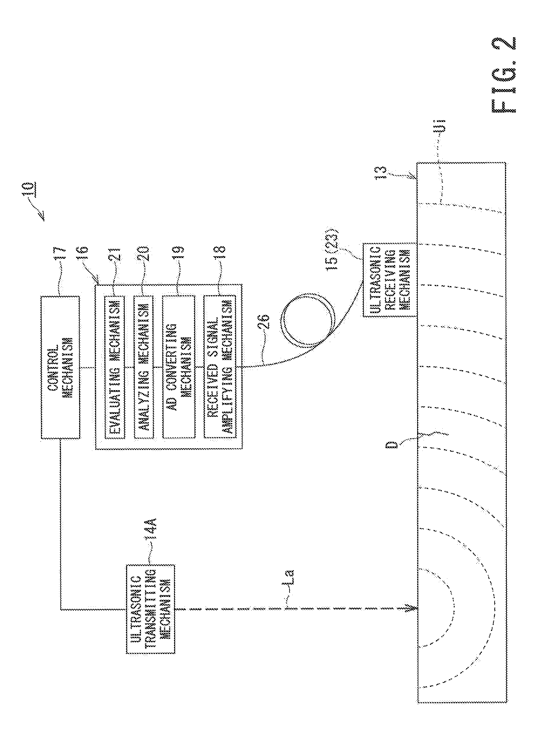
[0110]In the ultrasonic test equipment 10A of the second embodiment, since the ultrasonic transmitting mechanism 14 and the object to be tested 13 exist in the water 28, the water 28 functions as the acoustic medium (coupling). Thus, even when the ultrasonic transmitting mechanism 14 is not in close contact with the object to be tested 13, the ultrasonic wave Ui can propagate through the object to be tested 13.

[0111]When the defect D exists in the object to be tested 13, the nonlinear ultrasonic component generated only from the defect portion leaks into the water 28. Thus, a response from the defect D can be detected in the received ultrasonic wave in the ultrasonic receiving mechanism 15.

[0112]At this point, the hydrophone capable of detecting a broad band can be used as the ultrasonic receiving mechanism 15. The laser interferometer can also detect a response in a broad band.

[0113]The ultrasonic information of the received ultrasonic wave ...

third embodiment

Operation and Effect of Third Embodiment

[0122]In the ultrasonic test equipment 10B described in the third embodiment, the plurality of ultrasonic transmitting mechanisms 14 and the plurality of ultrasonic receiving mechanisms 15 are provided as shown in FIG. 15. Thus, the received ultrasonic wave Ur signal is obtained at a plurality of points. The signal is also obtained at a plurality of points by moving the ultrasonic transmitting mechanism 14 and the ultrasonic receiving mechanism 15 respectively by using the scanning mechanisms 30 as shown in FIG. 16.

[0123]The correlation processing is then performed by using the received waveform obtained at a plurality of points in the test, and a received waveform (hereunder, referred to as reference waveform) recorded on a recording device in advance and obtained when there is no defect in the object to be tested 13, that is, obtained from an object to be tested with no defect.

[0124]The reference waveform is prepared by, for example, acquiri...


PUM


Abstract

An ultrasonic test equipment includes: a signal generating mechanism that generates a voltage waveform; an ultrasonic transmitting mechanism that excites ultrasonic vibrations having a lower frequency than a predetermined frequency to an object to be tested; an ultrasonic receiving mechanism that receives an ultrasonic response from the object to be tested; an AD converting mechanism that digitizes the received ultrasonic waveform; an analyzing mechanism that performs frequency analysis of the digital ultrasonic waveform digitized by the AD converting mechanism; an evaluating mechanism that extracts a variation of a nonlinear ultrasonic component from a frequency component of the digital ultrasonic wave obtained by the frequency analysis, compares the variation with defect data information in a defect information database, identifies a physical quantity of defect information of the object to be tested, and evaluates a defect in the object to be tested; and a control mechanism that partly or entirely controls a measurement system.

Description

BACKGROUND OF THE INVENTION[0001]1. Field of the Invention[0002]The present invention relates to an ultrasonic test equipment capable of performing flaw detection in a wide range of an object to be tested, and an evaluation method for evaluating the tested result.[0003]2. Related Art[0004]Ultrasonic testing is a technique for nondestructively confirming soundness of a surface and an inner portion of a structural material that is an object to be tested, and is an indispensable testing technique in various fields. Particularly, in recent years, there is a demand for testing of a spot where ultrasonic testing has never been required in order to ensure safety of a plant structural object or the like. According to such demand, an improvement in efficiency as well as reliability is being required in the ultrasonic testing.[0005]Radiographic testing (RT) and ultrasonic testing (UT) are listed up as effective techniques for accurate sizing of a volume defect existing in a structural object....

Claims


Application Information

Patent Timeline
IPC IPC(8): G01N29/34
CPCG01N29/348G01N29/043G01N29/069G01N29/225G01N29/4427G01N29/46G01N2291/02491G01N2291/102
Inventor YAMAMOTO, SETSUSEMBOSHI, JUNYOSHIDA, MASAHIROMIURA, TAKAHIROWATANABE, KAZUMIOCHIAI, MAKOTONAGAI, SATOSHI
Owner KK TOSHIBA
Why Eureka
Try Eureka