Device for prevention of shunt stenosis

a technology for shunts and shunts, which is applied in the direction of balloon catheters, other medical devices, catheters, etc., can solve the problems of shunt stenosis, affecting the efficiency of hemodialysis, and affecting the flow of blood in the veins, so as to prevent shunt stenosis, prevent shunt stenosis, and improve hemodialysis efficiency.

Active Publication Date: 2014-09-11
MICROBOT MEDICAL LTD
View PDF6 Cites 8 Cited by
  • Summary
  • Abstract
  • Description
  • Claims
  • Application Information

AI Technical Summary

Benefits of technology

[0007]The present disclosure describes a new exemplary method and a kit or system for the prevention of venous stenosis associated with the use of hemodialysis AV shunts. The kit is simple in construction and simple in operation such that it can be used by auxiliary medical personnel, or even by the patient him / herself in the home setting, if dialysis is performed there. The kit may use a bifurcated needle, such as a Y-needle, for providing access to the shunt or blood vessel. The blood is generally drawn from the patient for transfer to the dialysis machine through a needle upstream of the Y-needle, and of the two arms of the Y-needle, one is used for returning the blood to the shunt or vein after treatment in the dialysis apparatus, while the other arm is used for inserting a device for cleaning the vein, the device being either an autonomous crawling device, or a passive tethered device moved down the vein by the blood flow. Thus, while the device is being inserted into one arm of the Y-needle, the dialysis can continue through the other arm while the cleaning process is performed. This Y-needle can be inserted either into the shunt itself or into the vein immediately below the point at which the shunt is joined to the vein. Insertion of the device into the same lumen with the returning blood flow is advantageous, since the stenosis generally occurs in the vein after the junction point with the shunt, where the blood flows back into the vein.

Problems solved by technology

However, the flow of blood in the veins, coming from the capillaries, is generally too slow for the flow required for efficient hemodialysis.
However, such shunts, both of the fistula and AV type, have a problem in that they are often associated with stenosis of the vein into which they are inserted, usually just downstream from the point where the shunt has been sewn into the vein, or the point where the artery and vein are sewn together.
Such venous narrowing often leads to clotting or thrombosis, and if untreated, could lead to complete blockage of the vein, often within less than a year of the insertion of the shunt.
However, this procedure is costly, involving complex instrumentation and x-ray surveillance generally available only in the hospital environment, generally has to be repeated at intervals of several months, and has the associated dangers of venous rupture if excess pressure is applied.
However, it should be emphasized that despite certain superficial similarity of some aspects of the implementations in this disclosure with balloon angioplasty, there is a significant difference between the present application and balloon angioplasty.
However, it is feasible that since the time taken to perform the cleaning procedure is very short, possibly of the order of only tens of seconds, the provision of blood flow relief passages may not be essential since such a short period without significant blood flow in that vein would not be detrimental to the patient or the dialysis procedure.

Method used


Image

  • Device for prevention of shunt stenosis
  • Device for prevention of shunt stenosis
  • Device for prevention of shunt stenosis

Examples


Embodiment Construction

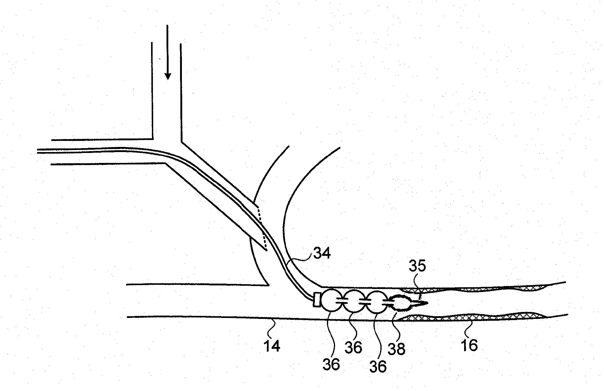
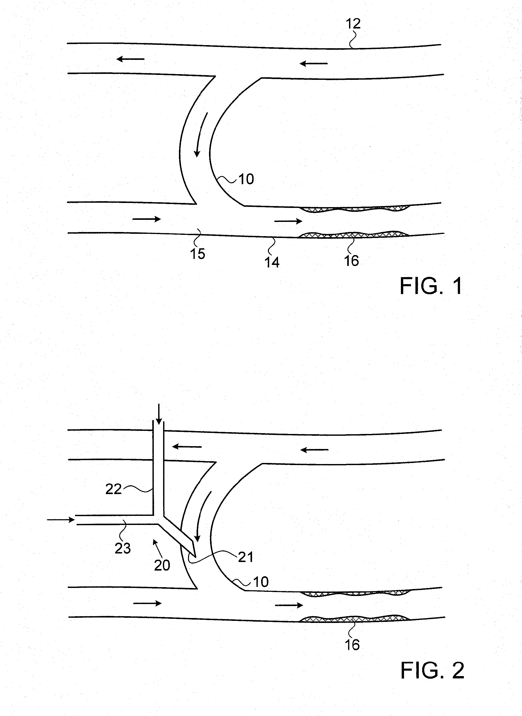
[0043]Reference is now made to FIG. 1, which illustrates schematically the layout of the vasculature in the forearm of the subject, with an arterial-venous shunt 10 installed between an artery 12 and a vein 14, as is customarily done for a subject undergoing a course of hemodialysis treatment. The arrows in the blood vessels and in the shunt show the direction of blood flow. The needle for withdrawing blood for sending to the dialysis machine can either be inserted into the shunt 10 itself, or into the vein immediately after the point at which the shunt joins the vein 15. In FIG. 1 there are shown a deposit of unwanted lesion tissue 16 in the vein, downstream from the shunt-vein joining point, resulting from stenosis of the vein supposedly associated with the presence of the dialysis shunt. In many cases, this plaque deposits extends for a distance of 1 to 2 cm from the shunt-vein junction 15.

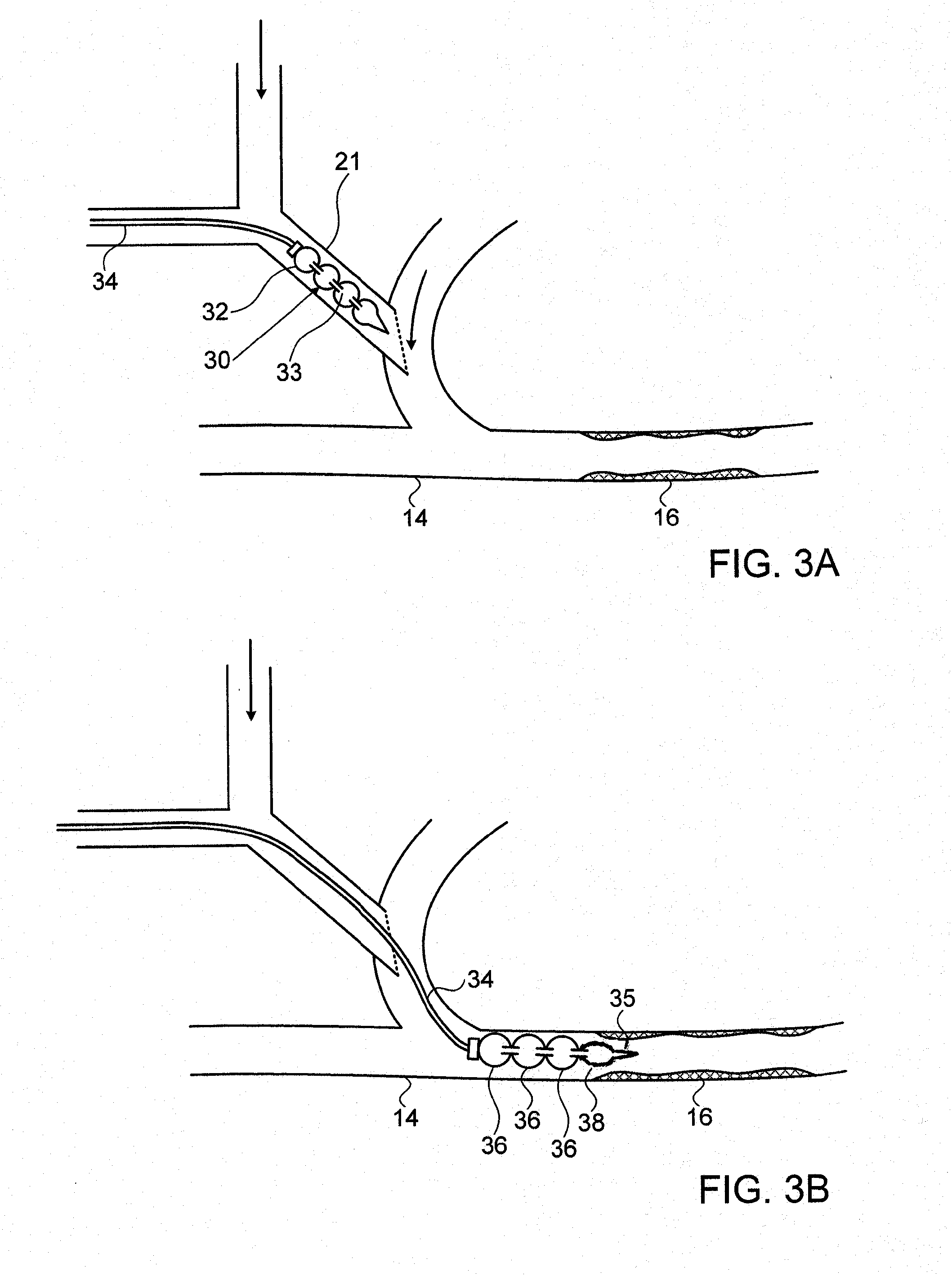
[0044]Reference is now made to FIG. 2, which illustrates schematically an exemplary kit for...


PUM


Abstract

A method and a kit for the prevention of venous stenosis associated with the use of hemodialysis AV shunts. The kit may use a bifurcated needle for providing access to the shunt or blood vessel. One of the arms is used for returning the blood to the subject after dialysis treatment, while the other arm is used for inserting a device for cleaning the vein, the device being either an autonomous crawling device, or a passive tethered device moved down the vein by the blood flow. The autonomous crawling device may be a series of sequentially inflatable chambers, the stenosis being cleared by pressure from the outer walls of the chambers when inflated and moved. The passive device may be an element having a flexible disc-like structure, whose flexible peripheral edge slides along the inner walls of the blood vessel, compressing or clearing the material attached thereto.

Description

FIELD OF THE INVENTION[0001]The present invention relates to the field of devices and methods for use in the prevention of stenosis in blood vessels, especially for use on blood vessels adjacent to a hemodialysis shunt.BACKGROUND OF THE INVENTION[0002]The extraction of blood for hemodialysis is generally performed on a vein. However, the flow of blood in the veins, coming from the capillaries, is generally too slow for the flow required for efficient hemodialysis. In order to ensure a sufficiently fast flow of blood in the vein, a procedure is used to join an adjacent artery to the vein, allowing arterial blood to flow directly into the vein, thereby boosting its flow rate. A commonly used site is a blood vessel of the arm, e.g. at the wrist or at the upper forearm. Due to the arterial pressure, the vein should increase in size and its walls thicken, such that it is then easier to put needles into this vein to extract and to return the blood. The arterial-venous (AV) join is general...

Claims


Application Information

Patent Timeline
Patent Type & Authority Applications(United States)
IPC IPC(8): A61M1/36
CPCA61M1/3655A61M2209/10A61M1/367A61M25/0116A61M25/0155A61M25/104A61M2025/1072A61M2025/109A61B17/320725A61M2025/1097A61M1/83A61M25/1011
Inventor SHECHTMAN, ADISHOHAM, MOSHEGADOT, HAREL
Owner MICROBOT MEDICAL LTD
Why Eureka
Try Eureka