Mobile Pelletizing System

a pelletizing system and mobile technology, applied in the field of mobile pelletizing systems, can solve the problems of wasting residual energy used in individual processing steps, occupying 20% of the total cost of pellets, and being most energy-intensive, and achieve the effect of new adaptability of component parts

Inactive Publication Date: 2014-09-18
BONFIRE BIOMASS CONVERSIONS
View PDF0 Cites 27 Cited by
  • Summary
  • Abstract
  • Description
  • Claims
  • Application Information

AI Technical Summary

Benefits of technology

[0008]To address these concerns, embodiments of the invention provide a system for in situ processing of biomass material to pellets. Provided in embodiments is a mobile pelletizing system (otherwise referred to as the MOPET pelletizing system) that is novel due to the arrangement, compactness and efficiency and novel adaptability of the component parts integrated together as a whole. The combination of these attributes allows mobility of the unit. There is nothing like this system in existence. Furthermore, the pellet mill in and of itself is novel and can be used as a stand-alone unit (i.e., as a stationary pellet plant) or it can be used in a mobile system as well.
[0009]Systems according to the invention improve on current stationary pelletizing operations in energy real-time adaptability, efficiency, maintainability, ease of operation, and operating costs. The system is mobile, energy efficient, and easy to set up and, as a result, reduces the logistical barriers for conversion of biomass to pellets in situ and allows conversion of a wide range of biomass materials. The system includes automated process controls for better product consistency and reorganizes the current process steps to improve overall energy efficiency and reduce in-process time requirements. The system improves upon the equipment that has been conventionally used to carry out biomass processing and uses process energy streams to reduce the overall cost of production. As a result of these improvements, the system may be self-contained and mobile for transport to sources of biomass at the point of origin.
[0011]The complete set of processing components may include an input for receiving biomass material into the system, a means for reducing the size of the biomass material preferably after it has been received into the system (but before is also acceptable), a blender for homogenizing the biomass material preferably after it has been reduced in size (but before is also acceptable), a dryer for drying the biomass material preferably after it has been homogenized (but before is also acceptable), a conditioner for conditioning the biomass material preferably after it has been dried (but before is also acceptable), a pellet mill for extrusion of biomass material to pellets preferably after it has been conditioned (but before is also acceptable), a cooler for cooling the pellets after they have been extruded, and an output for transporting the pellets out of the system preferably after they have been cooled (but before is also acceptable). The heat exchange network is capable of transferring heat from the engine and the cooler to components upstream in the process, ensuring more efficient processing as well as conservation of heat within the system. Due to this configuration, of having all modules disposed in a single housing and by re-capturing heat from some parts of the process and re-distributing the heat to other parts of the process, the total energy consumption of the entire process is greatly reduced.
[0012]The processing components are configured for the highest degree of energy efficiency and quality production of the overall system. For example, providing the drying components upstream of the conditioning and pelletizing components ensures pelletizing occurs at high temperatures, which has been shown to be correlated with greater pellet quality. Further, some of the processing components include adaptive feedback systems that prevent interruption of steady-state operation of the system due to blockages. Some of the components include sensors to ensure optimal processing has occurred. The invention also provides for a novel pellet mill and methods for operating a pellet mill, wherein the pellet mill components are reconfigured and optimized for more efficient processing as well as a feedback system for minimizing blockages. The invention also includes a grinder with a similar feedback system.

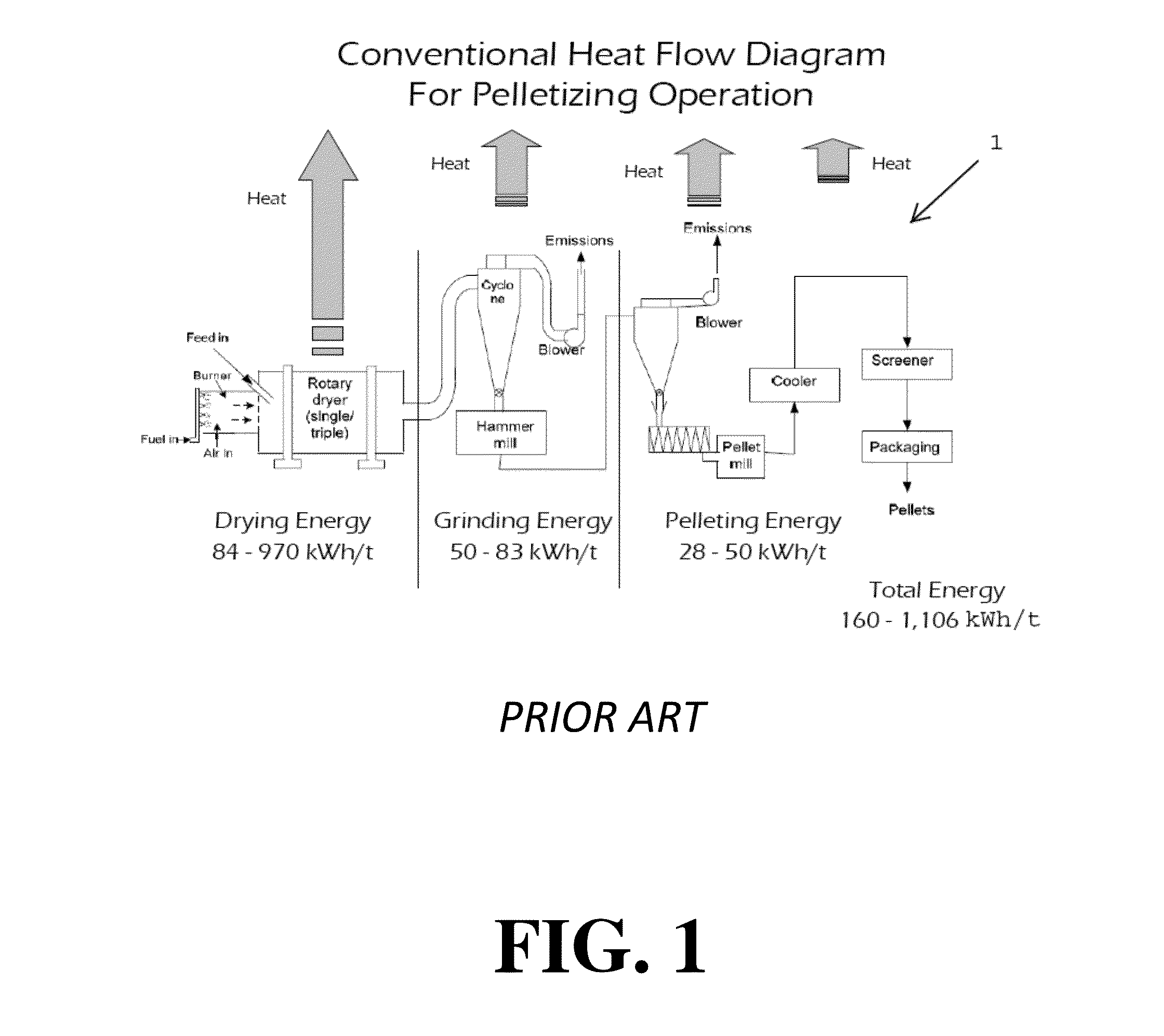
Problems solved by technology

Drying of the raw materials, an essential step of conventional techniques, is typically the most energy-intensive part of the process, typically representing 20% of the total cost of the pellet.
As current processes are not integrated, any residual energy used in the individual processing steps is wasted.
Such lack of integration contributes to the overall energy requirements of the pelletizing process.
However, current pellet mills are extremely sensitive to the quality of the input materials received.
While the processing steps prior to pelletizing are undertaken to ensure a consistent quality and amount of feedstock are fed to the mill, these processes are limited in efficacy, and often times improper drying, conditioning, or size reduction occurs prior to extrusion of pellets.
As a result, the pellet mill may either become overloaded or receive input of inconsistent composition, resulting in plugging of the mill which requires costly downtime and must be cleared manually to remedy.
This downtime is a large contributor to the inefficiency of these operations.
In addition to being energy intensive and inefficient, current pelletizing technology is limited in its ability to handle a variety of biomass, in part due to the potential for plugging, but also due to the fact that the inefficiency of these systems requires them to be stationary.
As a result, a number of potential sources of biomass end up going to waste due to the fact that there is currently no means for conversion of biomass at a site of origin.
Further, there are other potential sources of biomass that are not being utilized effectively such as those produced from weather / natural disasters, pest infestation, forest thinning operations, grasses from cash crops, and random bioorganic waste.
As a result, millions of tons of potential energy sources end up going to waste each year.

Method used


Image

  • Mobile Pelletizing System
  • Mobile Pelletizing System
  • Mobile Pelletizing System

Examples


examples

[0097]Die Design Extrusion Experiments

[0098]Since the die design's novel capabilities are key to optimizing pelletizing efficiency in certain embodiments, a series of experiments were done to study various changes to the die chamber for pelletizing. It was determined by these experiments that using other methods of construction for the die head of the pellet mill allows very different geometry possibilities beyond the standard reamed holes disclosed. For example, one experiment examined whether gradual tapers may mitigate some of the friction at the interface of the dies where the compression of the material begins. A second concept was studied wherein vents were introduced to the die chamber to release any unwanted matter, such as water. These concepts are shown in FIG. 17A.

example i

[0099]The extrusion mechanism was tested using the Nozzle Stack Assembly 7410. The assembly (shown in FIG. 17B) has a series of vents in the body of the die to allow the escape of moisture and steam while the material is under pressure. Ambient temperature was 55 F. No heat was used for either the die or the feedstock material. Feedstock was raw White Oak sawdust from using a chainsaw. Hydraulic pressure was set at 1700 psi. Material was fed into the chamber while the extrusion piston was cycled up and down using limit switches at either end of the stroke and a delay timer on the upper end of travel to allow feedstock to enter the chamber. Some of the feedstock fell through the Nozzle Stack at the beginning of cycling. This was blocked to allow the material to build up inside the stack. After the material began to compress in the stack, moisture in the form of water droplets came out of the side holes as predicted. This moisture indicated that the venting was functioning correctly a...

example ii

[0102]The extrusion mechanism was tested using the Nozzle Stack Assembly 7410. In this example, the piston diameter was reduced to about 0.45 square inches and the cylinder was sleeved to the same size. The nozzle stack was extended at the bottom and the top three segments were removed. This change was made to reduce the overall compression ratio at the throat. Ambient temperature was 45 F. No heat was used for either the die or the feedstock material. Hydraulic pressure was set at 1700 psi.

[0103]Material was fed into the chamber while the extrusion piston was cycled up and down using limit switches at either end of the stroke and a delay timer on the upper end of travel to allow feedstock to enter the chamber. Feedstock was raw White Oak sawdust from using a chainsaw and a variety of chopped dead leaves soaked in water (mainly Oak and Maple). The leaves were fed through without any sawdust. They exited the nozzle quite easily as there was little compression. The leaves did not form...


PUM

PropertyMeasurementUnit
particle sizesaaaaaaaaaa
sizeaaaaaaaaaa

Abstract

The present invention provides portable pelletizing systems for in situ processing of biomass material to pellets. Systems according to embodiments of the invention have a complete set of processing components and an engine for powering the processing components. The processing components are interconnected. Loading, unloading, and coordination of each of the processing components is automatically controlled through a controller. A heat exchange network is integrated with the engine and the processing components, wherein the heat exchange network transfers heat between the engine and the processing components. The system is self-contained and may be transported using a vehicle so that the system may receive biomass material of varying composition and moisture content at a point of origin. The complete set of processing components may include an input, a means for reducing the size of the biomass material, a blender, a dryer, a conditioner, a pellet mill, a cooler, and an output.

Description

CROSS REFERENCE TO RELATED APPLICATIONS[0001]This application claims priority to and the benefit of the filing date of U.S. Provisional Application No. 61 / 783,635 filed Mar. 14, 2013, the disclosure of which is hereby incorporated by reference herein in its entirety.BACKGROUND OF THE INVENTION[0002]1. Field of the Invention[0003]The present invention relates to the conversion of biomass material to pellets at a point of origin using a transportable system. Such pellets are a useful energy source.[0004]2. Description of the Related Art[0005]Pelletizing is the process of conversion of low density raw materials into higher density cubes of uniform composition that allow these materials to be more efficiently handled and utilized. While pelletizing had been widely used to make feedstuffs for pets and livestock, it is also used to compact biomass for use in the energy industry. Feedstock used to make pellets for energy include sawdust and scrap wood such as chips left over from hardwood ...

Claims


Application Information

Patent Timeline
Patent Type & Authority Applications(United States)
IPC IPC(8): C10L5/44
CPCC10L5/363C10L5/44B30B11/006B30B11/201B30B11/28B30B15/0094B30B15/26B30B15/281Y02E50/10Y02E50/30
Inventor MASON, THOMAS K.
Owner BONFIRE BIOMASS CONVERSIONS
Why Eureka
Try Eureka