
Symmetric dual piezoelectric stack microelectromechanical piezoelectric cantilever energy harvester

a piezoelectric and cantilever technology, applied in the direction of piezoelectric/electrostrictive transducers, generators/motors, transducer types, etc., can solve the problems of insufficient light, air movement and the environment does not include sufficient amounts of light, temperature fluctuation and/or pressure variation to power particular devices, etc., to achieve the effect of improving the power output of the piezoelectric energy harvester, improving the device performan

Inactive Publication Date: 2014-09-18
WIRELESS SENSOR SOLUTIONS LLC
View PDF2 Cites 22 Cited by
  • Summary
  • Abstract
  • Description
  • Claims
  • Application Information

AI Technical Summary

Benefits of technology

The present invention describes an energy harvester device that uses a special design with two layers of piezoelectric material. This design increases the amount of power that can be generated from the device. By controlling the flatness of the cantilever layer on which the piezoelectric layers are placed, researchers have been able to improve the performance of the device and make it more robust. This means that the device can generate more power and is more durable. The energy harvester can also be controlled more easily, resulting in better performance overall.

Problems solved by technology

In addition, battery replacement can be burdensome, particularly in larger networks with many nodes.
Some environments do not include sufficient amounts of light, air movement, temperature fluctuation, and / or pressure variation to power particular devices.
The additional piezoelectric stack is placed in this manner because during the process used to fabricate SOI wafers, direct bonding of two silicon wafers at high temperature, followed by grinding and polishing steps, makes it extremely difficult to place piezoelectric stacks in between the device and handle wafers.
Curl or lack of flatness in the cantilever due to poor management of residual stress in the layers can impact the performance of the MEMS energy harvester.

Method used


Image

  • Symmetric dual piezoelectric stack microelectromechanical piezoelectric cantilever energy harvester
  • Symmetric dual piezoelectric stack microelectromechanical piezoelectric cantilever energy harvester
  • Symmetric dual piezoelectric stack microelectromechanical piezoelectric cantilever energy harvester

Examples


Embodiment Construction

\

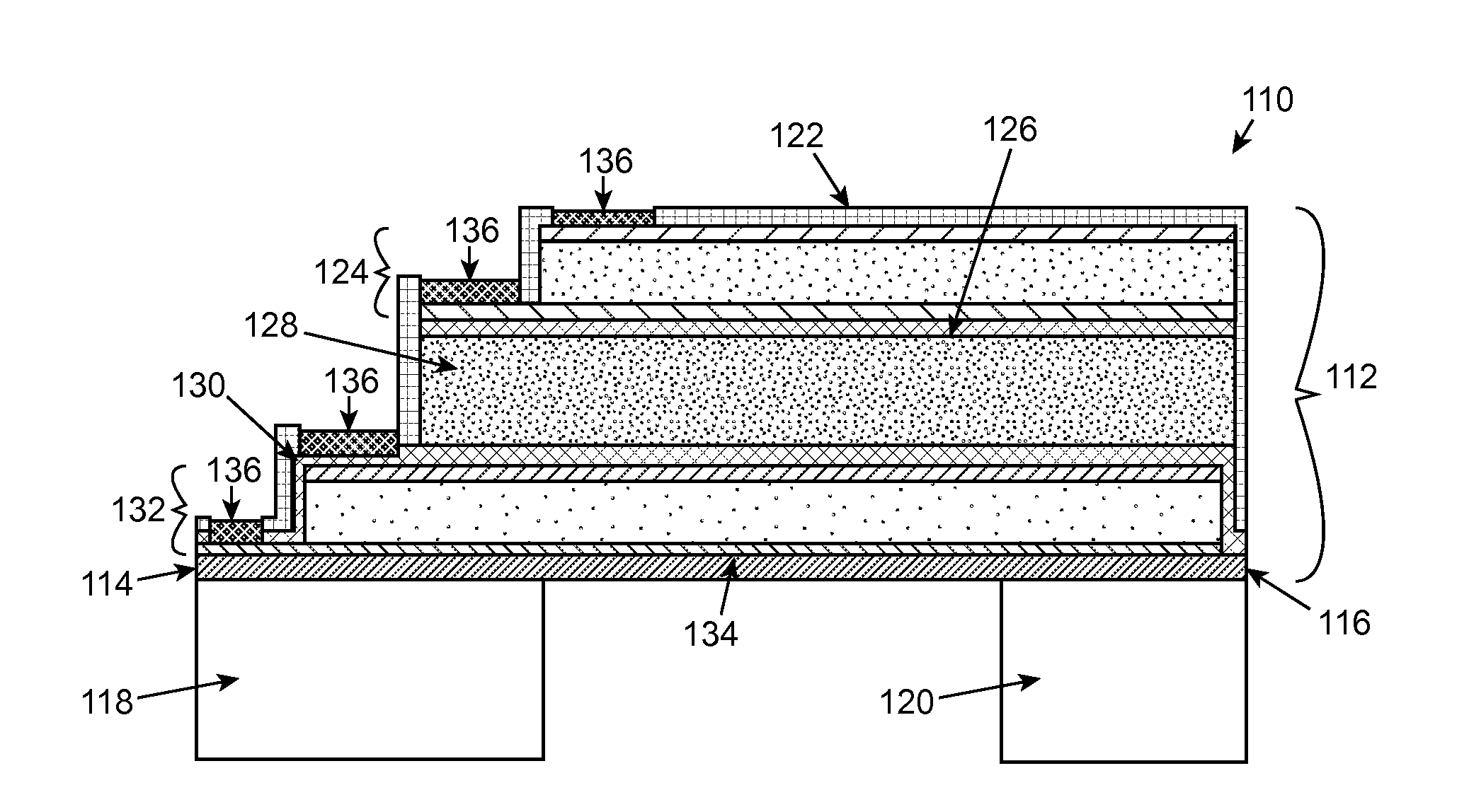
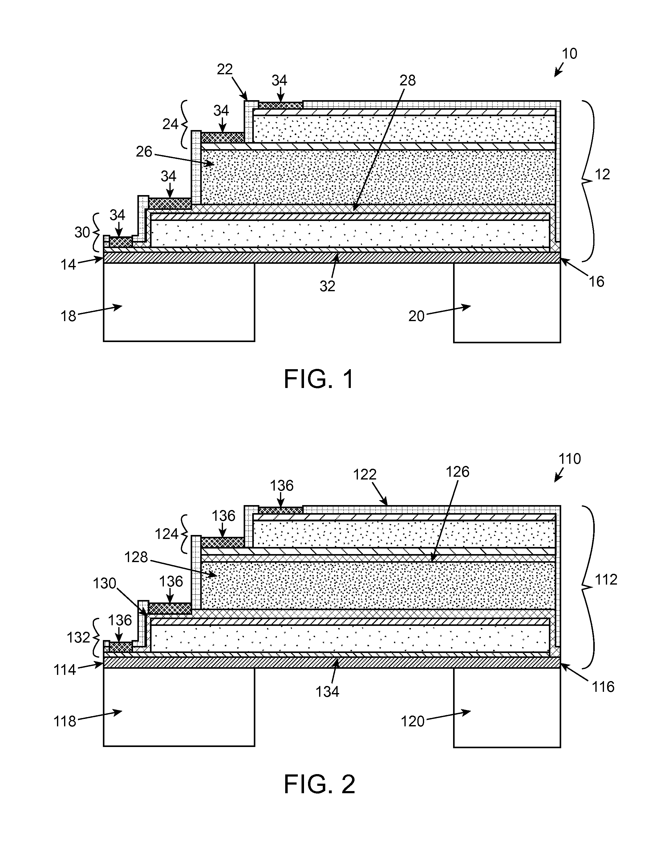
[0050]The present invention relates to a symmetric dual piezoelectric stack MEMS piezoelectric cantilever energy harvester device, a system comprising the energy harvester device, and methods of using and making the energy harvester device.

[0051]One aspect of the present invention relates to an energy harvester device comprising an elongate resonator beam extending between first and second ends. A base is connected to the resonator beam at the first end with the second end being freely extending from the base as a cantilever. A mass is attached to the second end of the elongate resonator beam. The elongate resonator beam comprises either: (1) a first oxide layer on a first piezoelectric stack layer over a cantilever layer on a second oxide layer over a second piezoelectric stack layer on a third oxide layer or (2) a first oxide layer on a first piezoelectric stack layer over a second oxide layer on a cantilever layer over a third oxide layer on a second piezoelectric stack over a f...


PUM

PropertyMeasurementUnit
Energyaaaaaaaaaa
Piezoelectricityaaaaaaaaaa

Abstract

The present invention relates to an energy harvester device comprising an elongate resonator beam extending between first and second ends. A base connected to the resonator beam at the first end with the second end being freely extending from the base as a cantilever. A mass is attached to the second end of the elongate resonator beam. The elongate resonator beam comprises either: (1) a first oxide layer on a first piezoelectric stack layer over a cantilever layer on a second oxide layer over a second piezoelectric stack layer on a third oxide layer or (2) a first oxide layer on a first piezoelectric stack layer over a second oxide layer on a cantilever layer over a third oxide layer on a second piezoelectric stack over a fourth oxide layer. Also disclosed is a system comprising an electrically powered apparatus and the energy harvester device, as well as methods of making and using the energy harvester.

Description

[0001]This application claims the benefit of U.S. Provisional Patent Application Ser. No. 61 / 780,176, filed Mar. 13, 2013, which is hereby incorporated by reference in its entirety.FIELD OF THE INVENTION[0002]The present invention relates to a symmetric dual piezoelectric stack microelectromechanical piezoelectric cantilever energy harvester.BACKGROUND OF THE INVENTION[0003]Reduction in both size and power consumption of integrated circuits has led to the proliferation of low power sensors and wireless technology. For example, there are a wide variety of devices using low-power sensors, electronics, and wireless transmitters, separately or in combination, including tablets; smartphones; cell phones; laptop computers; MP3 players; telephony headsets; headphones; routers; gaming controllers; mobile internet adaptors; wireless sensors; tire pressure sensor monitors; wearable sensors that communicate with tablets, PCs, and / or smartphones; devices for monitoring livestock; medical device...

Claims


Application Information

Patent Timeline
IPC IPC(8): H01L41/113H01L41/083H01L41/25
CPCH01L41/1136H01L41/25H01L41/083H02N2/188Y10T29/42H01L41/27H01L41/0831H01L41/0475H10N30/875H10N30/306H10N30/082H10N30/05H10N30/501
Inventor ANDOSCA, ROBERT G.
Owner WIRELESS SENSOR SOLUTIONS LLC
Learn More