Implantable Heart Pump Controller

a controller and heart pump technology, applied in the direction of heart stimulators, prostheses, therapy, etc., can solve the problems of increased medical costs, significant negative impact on patient quality of life, and high mechanical failure of pneumatically driven positive displacement pumps, so as to increase reduce the speed of ventricular assist devices

Active Publication Date: 2014-09-18
YALE UNIV +1
View PDF10 Cites 101 Cited by
  • Summary
  • Abstract
  • Description
  • Claims
  • Application Information

AI Technical Summary

Benefits of technology

[0008]In one embodiment, the controller is programmed to direct continuous flow. In another embodiment, the controller is programmed to direct pulsatile flow. In another embodiment, the controller further includes at least one electrode for receiving an EKG signal from the subject. In another embodiment, the controller is programmed to change the speed of the ventricular assist device based on the received EKG signal. In another embodiment, the controller is programmed to change the speed of the ventricular assist device based on a simulated EKG signal. In another embodiment, the controller is programmed to increase the speed of the ventricular assist device during a systole state in the heart of the subject. In another embodiment, the controller is programmed to decrease the speed of the ventricular assist device during a systole state in the heart of the subject. In another embodiment, the controller further comprises a receiver resonator for wireless energy transfer.

Problems solved by technology

Although showing a survival advantage, the earlier pneumatically driven positive displacement pumps showed high mechanical failure due to wear and tear associated with multiple moving parts and associated friction.
Despite the benefits of this technology, driveline-associated infections are a common and devastating complication (Sivaratnam and Duggan, 2002, ASAIO J, 48: 2-7; Simon et al., 2005, Clin Infect Dis., 40: 1108-15) that causes a significant negative impact on a patient's quality of life and increased medical cost (Slaughter et al., 2009, N Engl J Med, 361: 2241-51.

Method used


Image

  • Implantable Heart Pump Controller
  • Implantable Heart Pump Controller
  • Implantable Heart Pump Controller

Examples


experimental examples

[0045]The invention is further described in detail by reference to the following experimental examples. These examples are provided for purposes of illustration only, and are not intended to be limiting unless otherwise specified. Thus, the invention should in no way be construed as being limited to the following examples, but rather, should be construed to encompass any and all variations which become evident as a result of the teaching provided herein.

[0046]Without further description, it is believed that one of ordinary skill in the art can, using the preceding description and the following illustrative examples, make and utilize the present invention and practice the claimed methods. The following working examples therefore, specifically point out the preferred embodiments of the present invention, and are not to be construed as limiting in any way the remainder of the disclosure.

example 1

A Physiological, Pulsatile Driver for Continuous Flow Left Ventricular Assist Device (LVAD): Innovation Using an Implantable Ultra-Compact Microcontroller with a Wireless Graphical User Interface

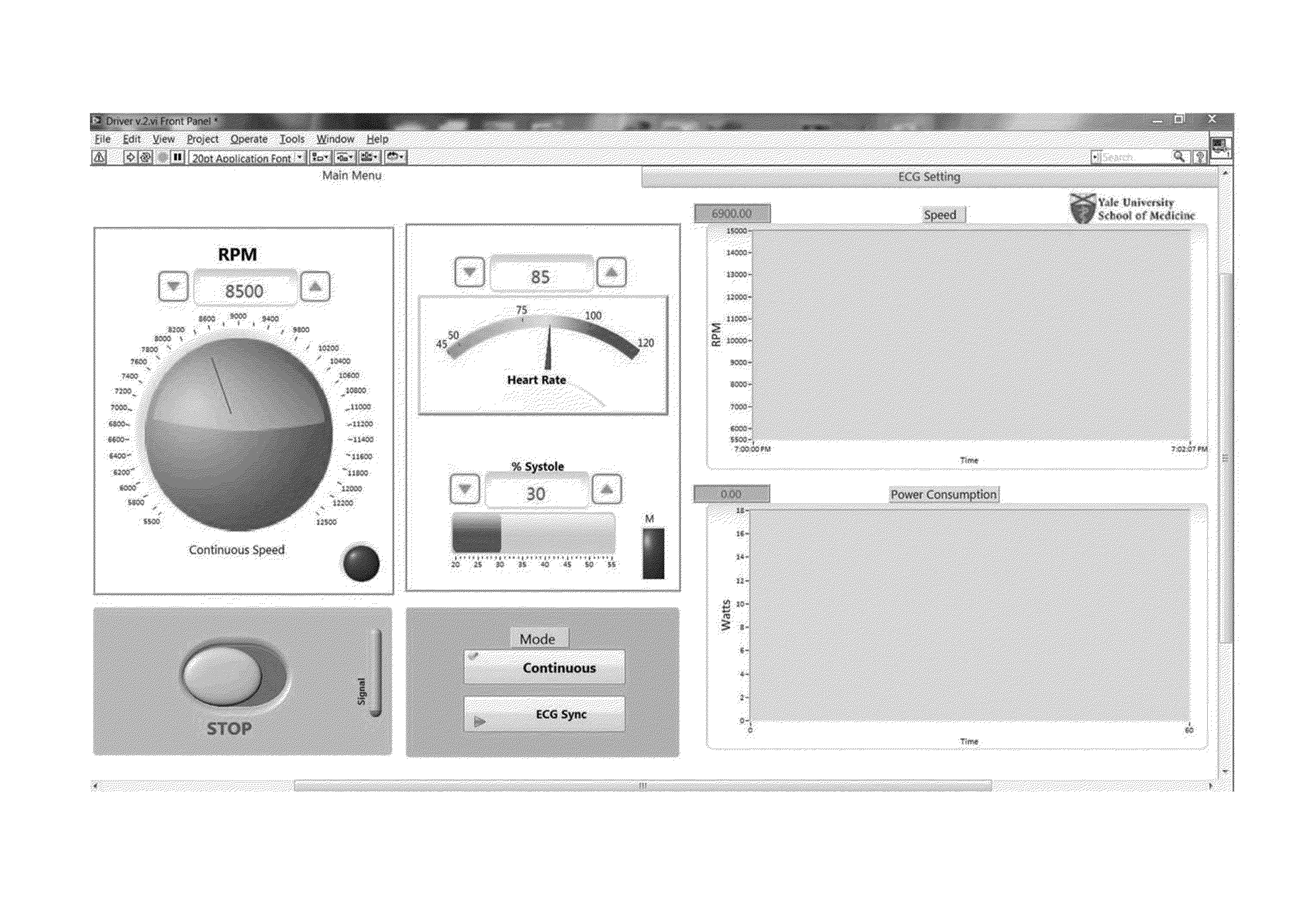
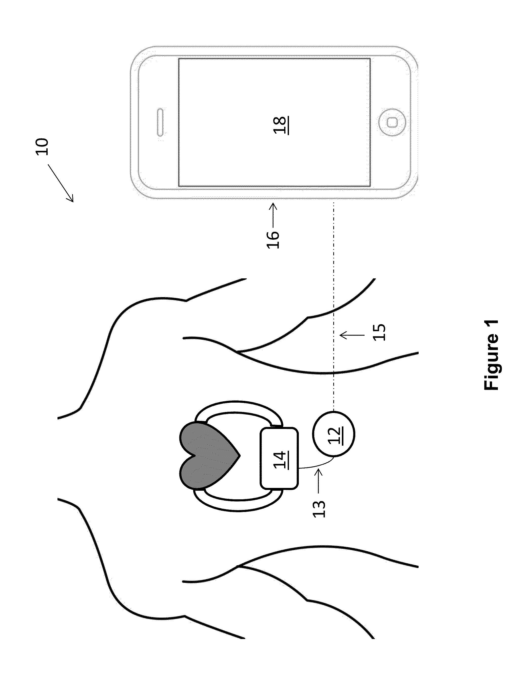
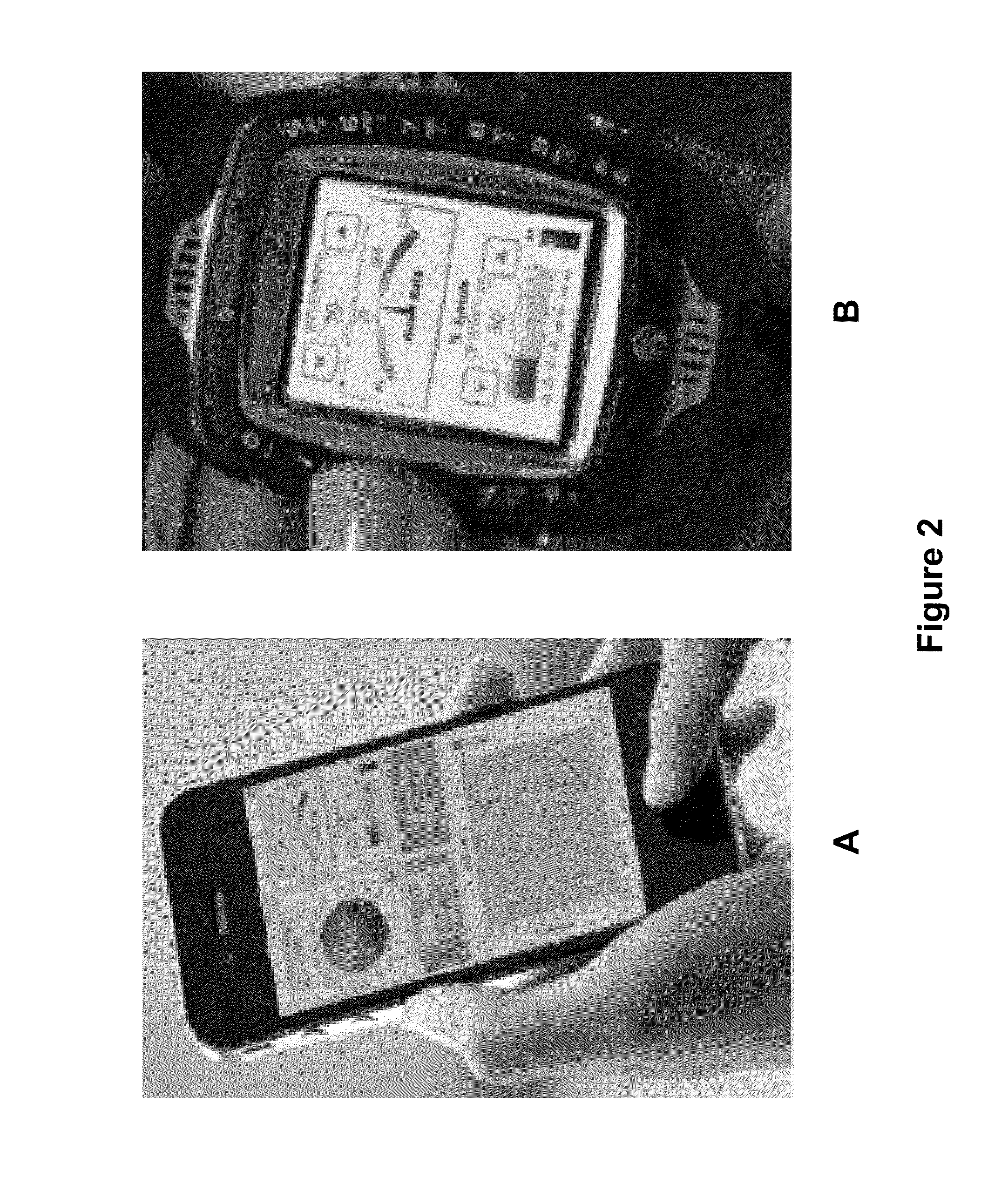
[0047]Described herein is the demonstration of an ultra-compact implantable microcontroller (UMC-Physio) (FIG. 5A) capable of pulsed operation in a rotary pump with wireless communication to a graphical user interface outside the body.

[0048]A three phase axial pump (HeartMate II) was used with an inline controller designed on an ultra-compact printed circuit board with embedded wireless algorithm to establish a communication network between the UMC-Physio and a graphical user interface to display the information and configuration settings on a computing device, such as a smartphone (FIG. 5B).

[0049]Signal processing and filtering methods were employed to analyze EKG signal and to adjust speed during systole and diastole for a co-pulsation, counter-pulsation or a fixed mode operation. Flow was...

example 2

Implantable Physiologic Controller for Left Ventricular Assist Devices with Telemetry Capability

[0051]Rotary type left ventricular assist devices have mitigated the problem of durability associated with earlier pulsatile pumps and demonstrated improved survival. However, the compromise is the loss of pulsatility due to continuous flow and retained percutaneous driveline leading to increased mortality and morbidity. Lack of pulsatility is implicated in increased gastrointestinal bleeding, aortic incompetence, and diastolic hypertension. Presented herein is a novel, wirelessly powered, ultra-compact, implantable physiologic controller capable of running a left ventricular assist device in a pulsatile mode with wireless power delivery.

[0052]The schematic of the presently described system was laid out on a circuit board to wirelessly receive power and run a left ventricular assist device with required safety and backup measures. An antenna and wireless network for telemetry was embedded...


PUM


Abstract

The present invention provides devices, systems, and methods for control of ventricular assist devices. The invention includes an implantable controller that is operatively programmed to direct physiological flow through a ventricular assist device that is substantially synchronized to the cardiac cycle of the subject. The implantable controller is also communicatively connected to an external control unit, such that the implantable controller can transmit data to the external control unit, and instructions can be sent from the external control unit to the implantable controller.

Description

CROSS-REFERENCE TO RELATED APPLICATIONS[0001]This application claims priority to U.S. Provisional Application No. 61 / 782,663 filed on Mar. 14, 2013, the contents of which are incorporated by reference herein in their entirety.BACKGROUND OF THE INVENTION[0002]By 2030, it is anticipated that 10 million people in the United States will live with heart failure (1 / 33 people) (Heidenreich et al., 2013, Crit Heart Fail, 6: 606-19; Roger et al., 2012, Circulation, 125: e2-220. However, the available donor hearts remain stagnant at approximately 2000 per year (Stehlik et al., 2010, J Heart Lung Transplant, 39: 1089-103). In recent years, implantable left ventricular assist devices (LVADs) have offered another option to this ill population. Although showing a survival advantage, the earlier pneumatically driven positive displacement pumps showed high mechanical failure due to wear and tear associated with multiple moving parts and associated friction. The technologic improvement of rotary pum...

Claims


Application Information

Patent Timeline
Patent Type & Authority Applications(United States)
IPC IPC(8): A61M1/10
CPCA61M1/1086A61M2205/3507A61M2205/3523A61M2205/52A61M2205/8206A61M2205/8243A61M60/148A61M60/232A61M60/237A61M60/178A61M60/538A61M60/515
Inventor BONDE, PRAMODASGARI, SIAVASHSMITH, JOSHUA REYNOLDSWATERS, BEN
Owner YALE UNIV
Why Eureka
Try Eureka