Colored composition and image display structure

a color composition and image display technology, applied in the direction of instruments, non-metal conductors, conductors, etc., can solve the problems of dyes that do not ensure satisfactory solubility in non-polar solvents, dyes that do not provide color reproducibility fully satisfactory, and the solubility of methine dyes, anthraquinone dyes or azomethine dyes is maintained in a more favorable manner, excellent optical shutter properties, and excellent display contrast

Active Publication Date: 2014-10-02
FUJIFILM CORP
View PDF2 Cites 9 Cited by
  • Summary
  • Abstract
  • Description
  • Claims
  • Application Information

AI Technical Summary

Benefits of technology

[0114]In a case in which the colored composition of the invention is used for electrowetting displays, the dye, other than the methine dye according to the invention, the anthraquinone dye according to the invention and the azomethine dye according to the invention, that is optionally contained in the colored composition of the invention may be freely selected from dyes that dissolve in non-polar solvents such as aliphatic hydrocarbon solvents. Specific examples thereof include Oil Blue N (alkylamine-substituted anthraquinone), Solvent Green, Sudan Red and Sudan Black.
[0116]The colored composition of the invention includes at least one non-polar solvent. Here, the non-polar solvent means a solvent having low dielectric constant (so-called apolar solvent).
[0117]The non-polar solvent as employed in the invention is a solvent that dissolves the above-described dye, and specific examples thereof include aliphatic hydrocarbon solvents (preferably, having from 6 to 30 carbon atoms) such as n-hexane, n-decane, n-dodecane, n-tetradecane and n-hexadecane.
[0118]The colored composition of the invention includes a non-polar solvent, and may further include a solvent other than non-polar solvents, to the extent that the effects of the present invention are not impaired.
[0119]In the invention, the content of non-polar solvent in the colored composition of the invention is preferably 70% by mass of higher, more preferably 90% by mass of higher, with respect to the total solvent amount in th

Problems solved by technology

However, the conventional dyes that have been proposed as dyes for use in image display applications (for example, displays based on an electrowetting method) have hues that are not fully satisfactory, and color reproducibility provided by the dyes are not fully satisfactory, either.
In addition, those dyes do not ens

Method used


Image

  • Colored composition and image display structure
  • Colored composition and image display structure
  • Colored composition and image display structure

Examples


example 1

[0252]The dye shown above as Exemplary Compound D2-1 was dissolved in n-hexane as a solvent to make a 3% by mass solution, so that a colored composition (ink) was prepared. The colored composition (ink) obtained was evaluated with respect to its color, absorption maximum wavelength (λ max), absorbance (abs) and absorption coefficient (∈), and solubility (% by mass) of the dye in a solvent. The evaluation results are shown in Table 1.

[0253]Evaluation Method for Each Property

[0254]1. Color of Colored Composition

[0255]The color of the colored composition was visually evaluated.

[0256]2. Absorption Maximum Wavelength, Absorbance and Absorption Coefficient of the Colored Composition

[0257]The absorption maximum wavelength (λmax) and the absorbance (abs) of the colored composition were measured using a visible-light spectrophotometer (trade name: UV-1800PC, manufactured by Shimadzu Corporation). The absorption coefficient (∈) was calculated based on the Lambert-Beer law.

[0258]3. Solubility ...

examples 14 and 15

Preparation of Black Composition

[0282]Dyes selected from the group consisting of Exemplary compound D8-2 and Dye M-1 (the structure of which is shown below), which are dyes according to the invention, and Dyes Y-1 to Y-3, C-1 and C-2, each of which is not a mixture of stereoisomers, were dissolved in n-decane, such that colored compositions 1 and 2 having the following compositions 1 and 2, respectively, were obtained.

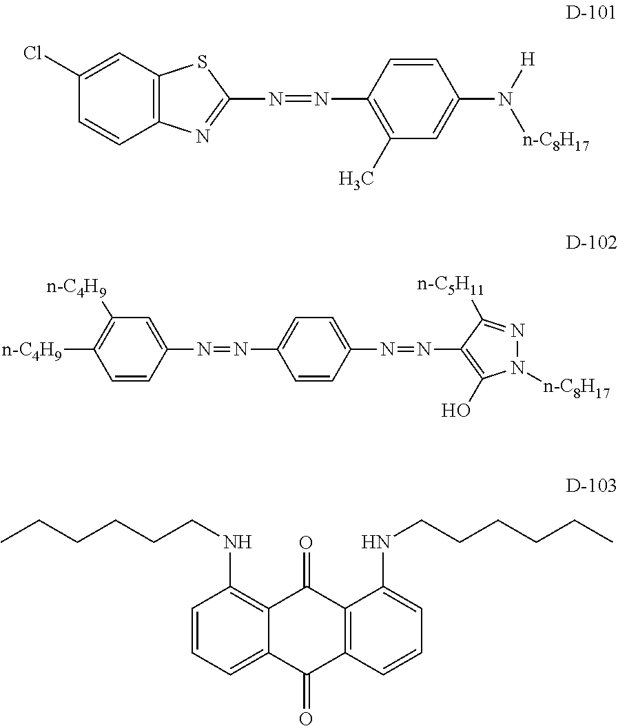
[0283]The structures of the dyes other than Exemplary Compound D8-2 are shown below. In Dye M-1, “C6H13” represents a normal alkyl group. Further, in the following structures, “Me” represents a methyl group, “Et” represents an ethyl group and “t-Bu” represents a tert-butyl group.

[0284]Colored Composition 1

[0285]Composition 1

Dye Y-2260 mgDye M-1 (dye according to the invention)200 mgDye D8-2 (dye according to the invention)160 mgDye C-1300 mgDye C-2100 mgn-decane980 mg

[0286]The colored composition 1 obtained was black. The dynamic viscosity of the colored composition 1 ...

examples 16 to 20

Preparation of Test Cell

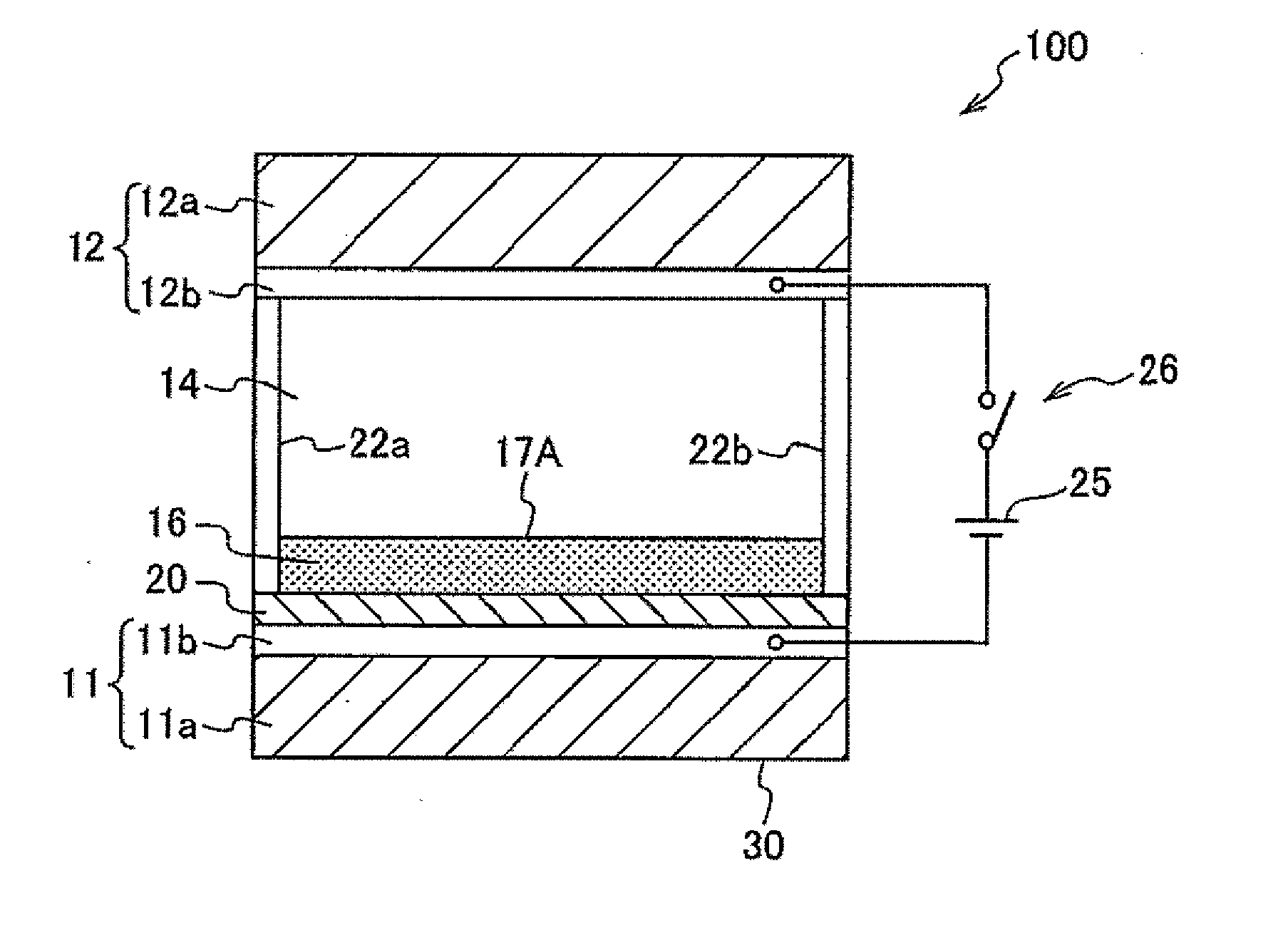
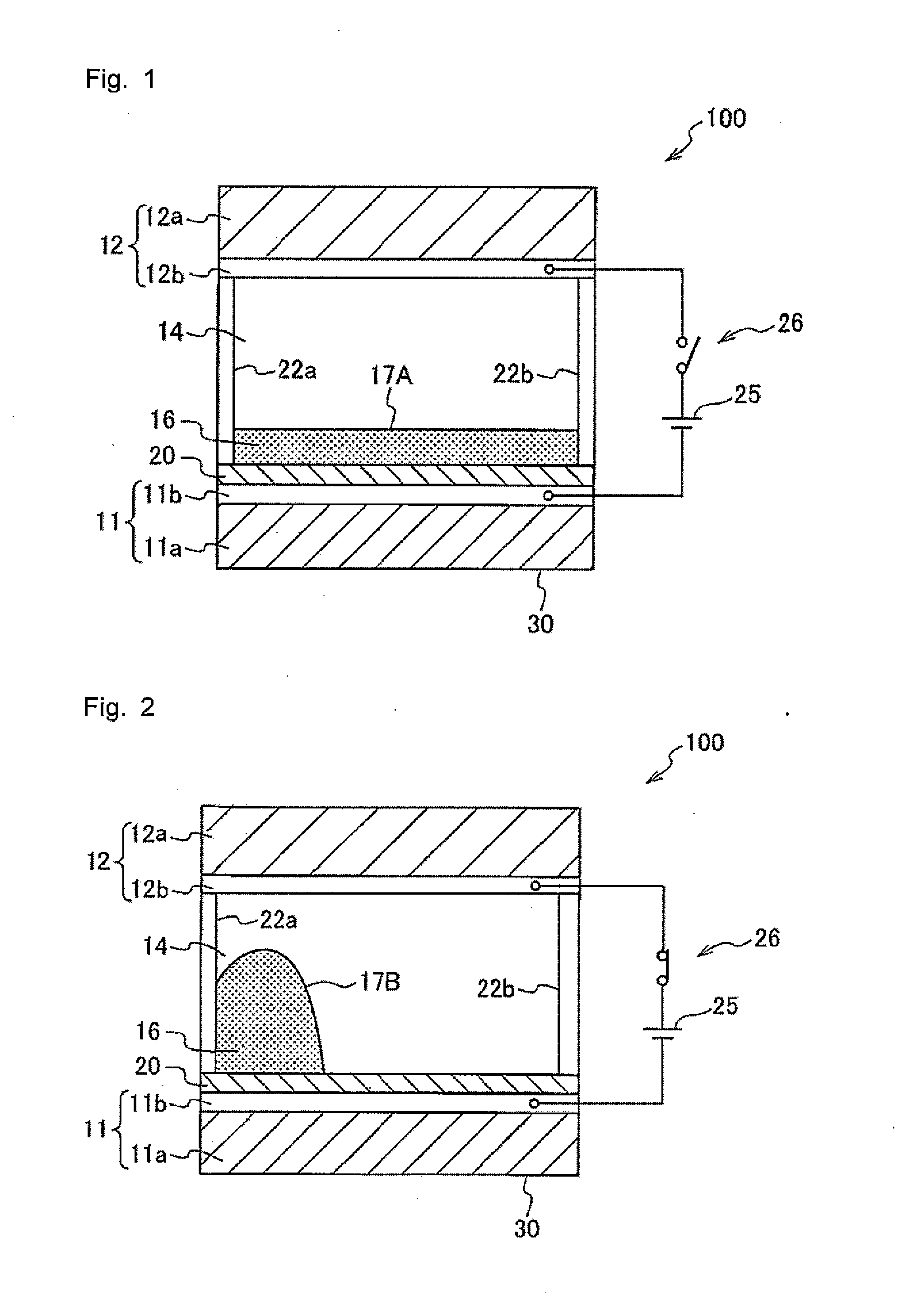
[0291]A glass substrate (10 mm×10 mm) on which an indium tin oxide (ITO) film having a thickness of 100 nm was formed as a transparent electrode was prepared. On the surface of the ITO film, a fluoropolymer (tradename: CYTOP manufactured by Asahi Glass Co., Ltd., model CTL-809M) was coated in a thickness of 600 nm, thereby forming a fluoropolymer layer as a hydrophobic insulating film. Subsequently, a picture frame-shaped silicone rubber wall left after cutting out a 8 mm×8 mm×50 μm-sized piece from the central portion of a 1 cm×1 cm-sized silicone rubber (a sealing material having a thickness of 50 μm; SILIUS (tradename) manufactured by Fuso Rubber Co., Ltd.) was placed on the fluoropolymer layer, thereby forming a display area. A colored composition was injected, in a thickness of 4 μm, into the space enclosed by the silicone rubber wall. Onto the injected colored composition, ethyleneglycol (hydrophilic liquid) was further injected in a thickness of 46 μm....


PUM


Abstract

A colored composition includes: (A) a dye that is selected from the group consisting of a methine dye, an anthraquinone dye and an azomethine dye, and that is a mixture of stereoisomers; and (B) a non-polar solvent.

Description

CROSS-REFERENCE TO RELATED APPLICATIONS[0001]This application is a continuation application of International Application No. PCT / JP / 2012 / 084270, filed Dec. 26, 2012, the disclosure of which is incorporated herein by reference in its entirety. Further, this application claims priority from Japanese Patent Application No. 2011-284270, filed Dec. 26, 2011, the disclosure of which is incorporated herein by reference in its entirety.TECHNICAL FIELD[0002]The present invention relates to a dye-containing colored composition and an image display structure.BACKGROUND ART[0003]In recent years, many organic dyes have been used in display materials, optical recording media, inkjet recording material, etc. In a case in which a dye is used in a coating process or an inkjet recording process, the dye is required to have a high molar absorption coefficient as well as high solubility in solvents in order to increase coloring efficiency.[0004]Recently, displays utilizing an electrowetting method (EWD...

Claims


Application Information

Patent Timeline
IPC IPC(8): G02B26/00G02F1/167
CPCC09B23/04C09B55/002C09B55/003G02F2001/1678C09B1/16G02B26/005G02F1/167C09B67/0083C09B55/00C09B55/009
Inventor KATO, TAKASHIISHIWATA, YASUHIRONAITO, HIROYUKI
Owner FUJIFILM CORP
Why Eureka
Try Eureka