Solid electrolyte
a solid electrolyte and electrolyte technology, applied in the field of solid electrolyte, can solve the problems of limited use of solid electrolyte in a high dew point environment and greatly reduced ionic conductivity
- Summary
- Abstract
- Description
- Claims
- Application Information
AI Technical Summary
Benefits of technology
Problems solved by technology
Method used
Image
Examples
production example 1
Production of Lithium Sulfide (Li2S)
[0258]The production and purification of lithium sulfide were conducted in the same manner as in Examples described in WO2005 / 040039A1. Specifically, it was conducted as shown below.
(1) Production of Lithium Sulfide
[0259]3326.4 g (33.6 mol) of N-methyl-2-pyrrolidone (NMP) and 287.4 g (12 mol) lithium hydroxide were charged in a 10-liter autoclave with an impeller attached, and heated to 130° C. at 300 rpm. After heated, hydrogen sulfide was blown into the resulting liquid at a supply rate of 3 liter / min for 2 hours.
[0260]Subsequently, this reaction liquid was heated (200 cc / min) under nitrogen stream to allow a part of reacted hydrogen sulfide to be hydrodesulfurized. With an increase in temperature, water generated as a side product due to the reaction of the above-mentioned hydrogen sulfide and lithium hydroxide began to evaporate. The evaporated water was condensed using a condenser and removed to the outside the system. Since the temperature o...
production example 2
Electrolyte Precursor (Sulfide-Based Glass: Li2S / P2S5=75 / 25): MM Method
[0263]An electrolyte precursor (sulfide-based glass) was produced using lithium sulfide which had been produced in Production Example 1 according to the method described in Example 1 in WO07 / 066,539.
[0264]Specifically, 0.383 g (0.00833 mol) of lithium sulfide which had been produced in Production Example 1 and 0.618 g (0.00278 mol) of phosphorus pentasulfide (manufactured by Sigma-Aldrich Co. LLC.) were sufficiently mixed. The mixed powder, 10 zirconia balls and a planetary ball mill (P-7, manufactured by Fritsch) were charged in an alumina pot. The pot was completely closed and was filled with nitrogen, thereby to attain nitrogen atmosphere.
[0265]For the initial several tens of minutes, lithium sulfide and phosphorus pentasulfide were sufficiently mixed with the planetary ball mill being rotated at a low speed (100 rpm). Then, the rotation speed of the planetary ball mill was gradually raised until 370 rpm. The ...
production example 3
Electrolyte Precursor (Sulfide-Based Glass: Li2S / P2S5=70 / 30): MM Method
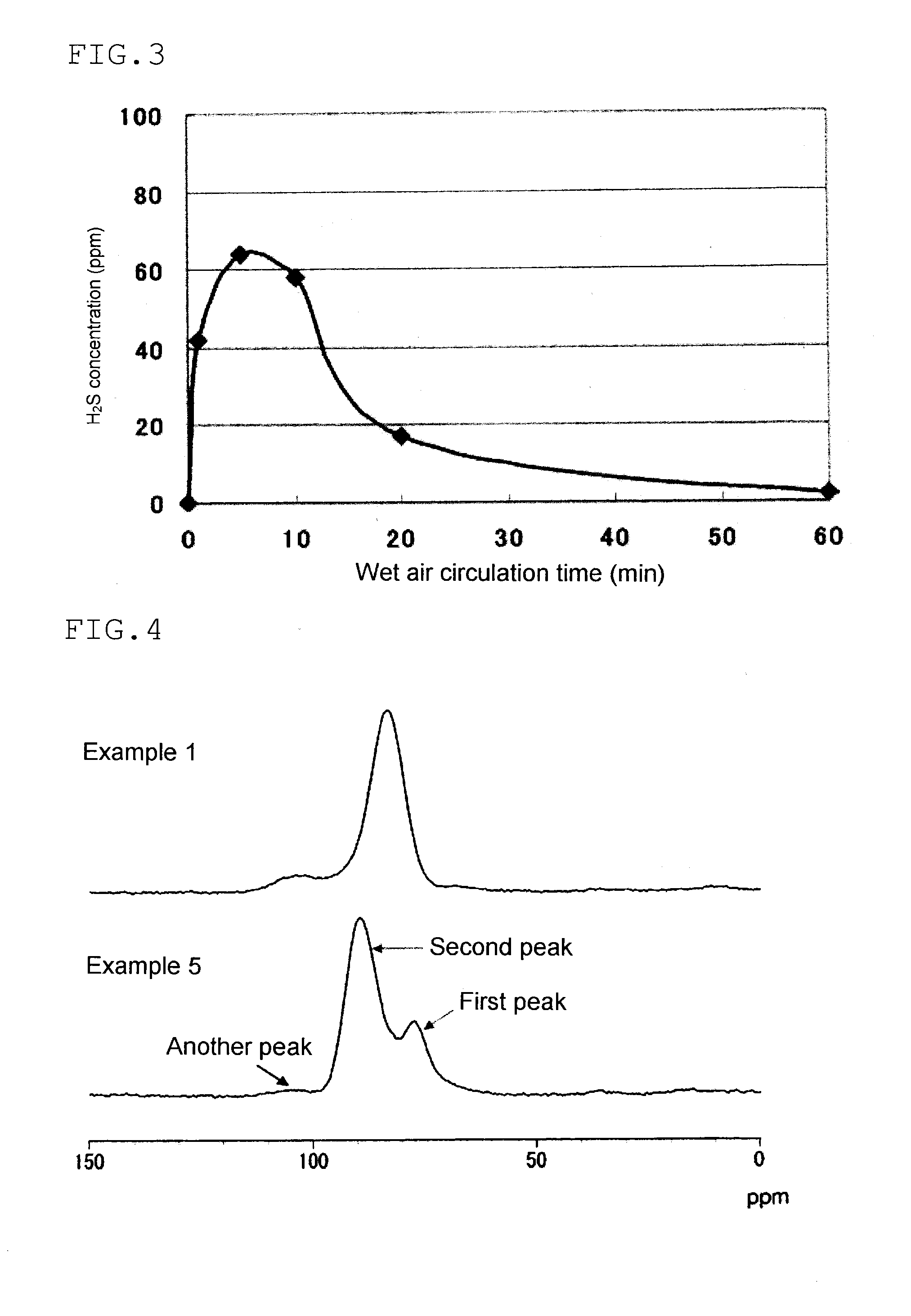
[0269]Sulfide-based glass was obtained in the same manner as in Production Example 2, except that the amount of lithium sulfide was changed to 0.325 g (0.00707 mol), and the amount of phosphorous pentasulfide was changed to 0.675 g (0.00303 mol). Table 1 shows the result of 31P-NMR measurement, the ionic conductivity σ, and the average value of the hydrogen sulfide concentration of the sample obtained. Tg and Tc are shown in Table 2.
PUM
| Property | Measurement | Unit |
|---|---|---|
| Temperature | aaaaa | aaaaa |
| Temperature | aaaaa | aaaaa |
| Temperature | aaaaa | aaaaa |
Abstract
Description
Claims
Application Information
 - R&D
- Intellectual Property
- Life Sciences
- Materials
- Tech Scout
- Unparalleled Data Quality
- Higher Quality Content
- 60% Fewer Hallucinations
Browse by: Latest US Patents, China's latest patents, Technical Efficacy Thesaurus, Application Domain, Technology Topic, Popular Technical Reports.
© 2025 PatSnap. All rights reserved.Legal|Privacy policy|Modern Slavery Act Transparency Statement|Sitemap|About US| Contact US: help@patsnap.com


