Constructing method for concrete cylinder of construction steel bar of high-rise steel structure

a construction method and steel bar technology, applied in the field of building construction, can solve the problems of high transportation pressure, poor wallboard forming quality, high risk in high-altitude setup and removal operations, etc., and achieve the effects of safe construction, good project quality, and fast construction

Active Publication Date: 2014-10-16
ZHEJIANG CONSTR ENG GRP CO LTD
View PDF7 Cites 51 Cited by
  • Summary
  • Abstract
  • Description
  • Claims
  • Application Information

AI Technical Summary

Benefits of technology

[0011]To overcome the above defects in the existing construction method for a reinforced concrete core cylinder, provided in the present invention is a constructing method for a concre

Problems solved by technology

In conventional construction methods for a high-rise steel structure building reinforced concrete cylinder, a steel cylinder fastener-type cantilever scaffold is used for protection at the outer side of the cylinder and a steel cylinder fastener-type formwork support structure is used at the inner side, which results in such obvious defects as high risk in high-altitude setup and removal operations, poor wallboard forming quality caused by unstable outer wall formwork supporting system, and high transportation pressure caused by frequent material circulation, etc.
1. In the conventional cylinder construction method, the steel cylinder fastener-type cantilever scaffold is used for protection and needs to be set up and removed repeatedly at high altitude, so there is a high safety risk in high-altitude operations and a high pressure of vertical material transportation; especially, in the case that a structure of steel tubular column+steel beam+profiled steel sheet composite slab is adopted at the periphery, plenty of contradictions could arise between hoisting of steel structure members and vertical material transportation.
2. In the conventional cylinde

Method used


Image

  • Constructing method for concrete cylinder of construction steel bar of high-rise steel structure
  • Constructing method for concrete cylinder of construction steel bar of high-rise steel structure
  • Constructing method for concrete cylinder of construction steel bar of high-rise steel structure

Examples


Embodiment Construction

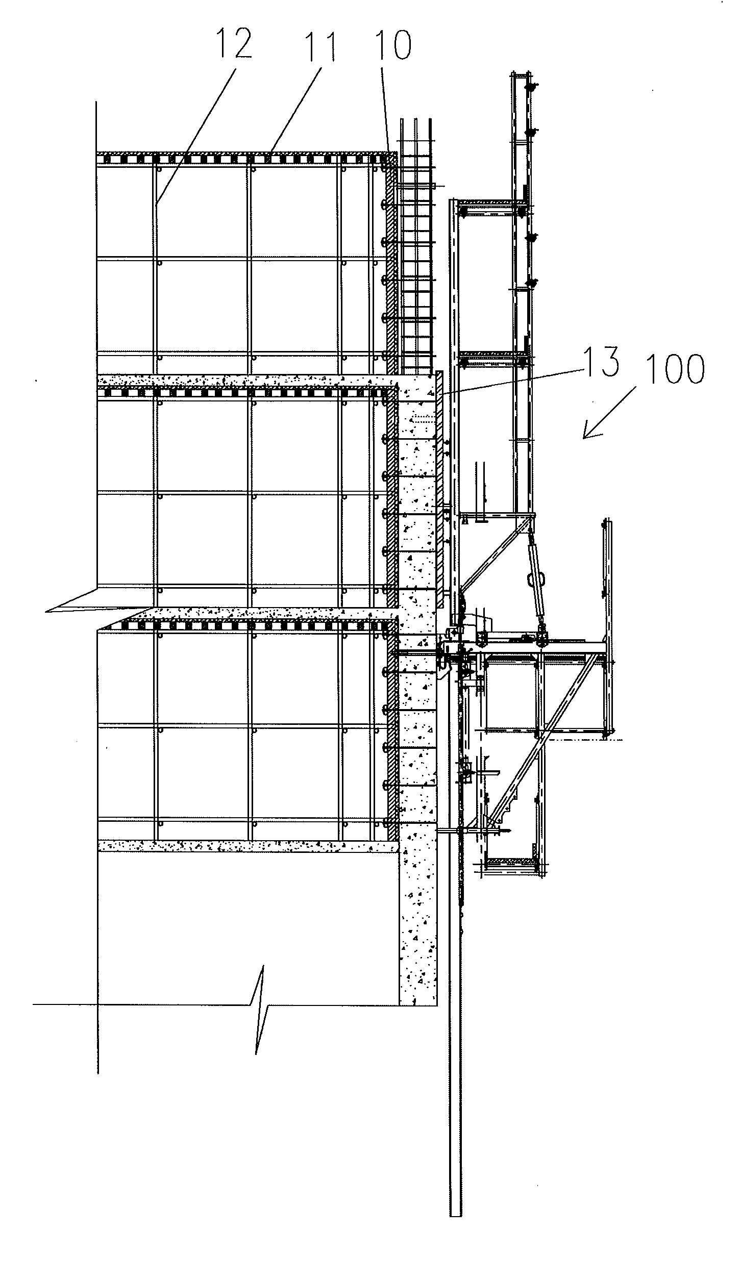
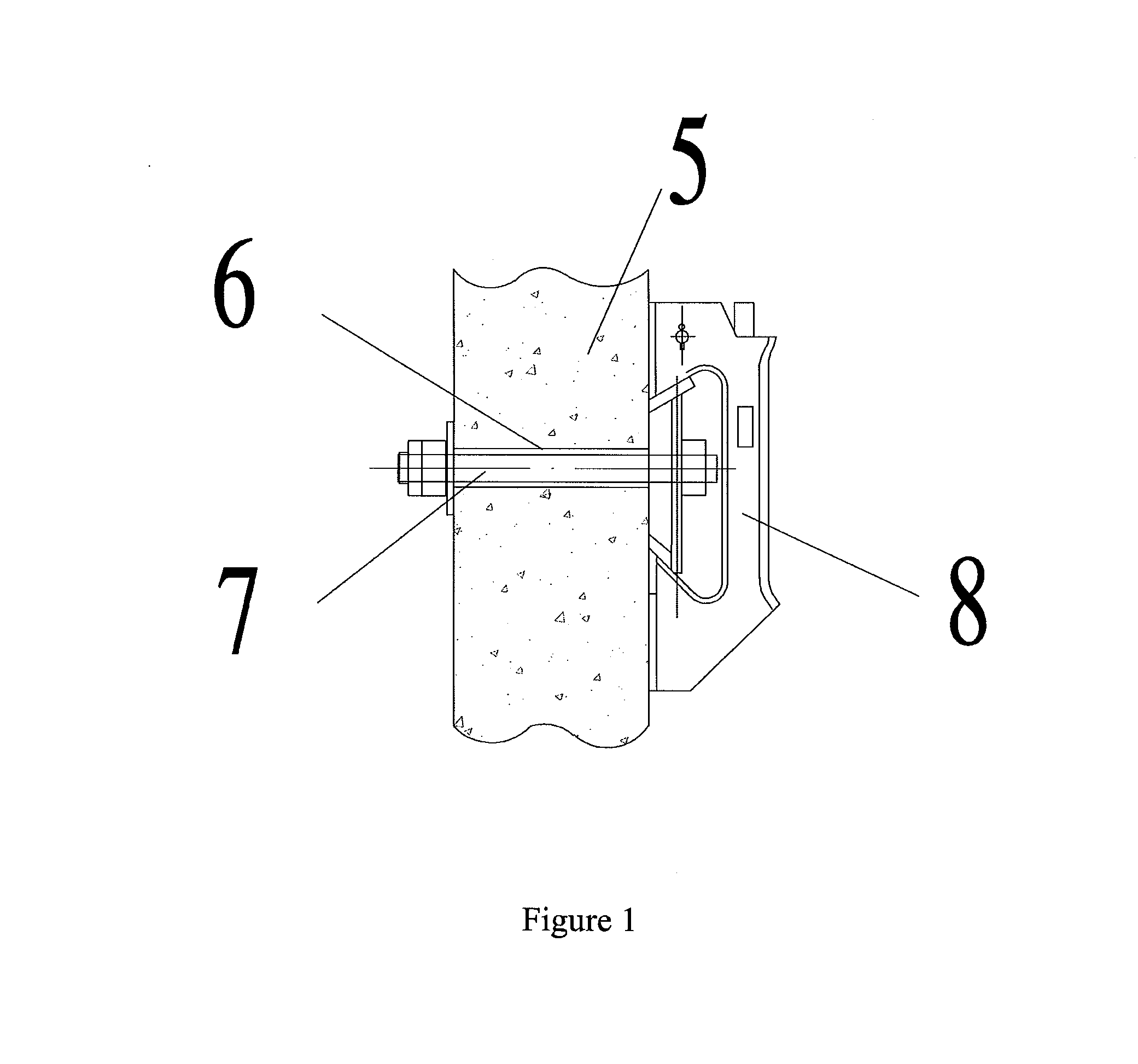
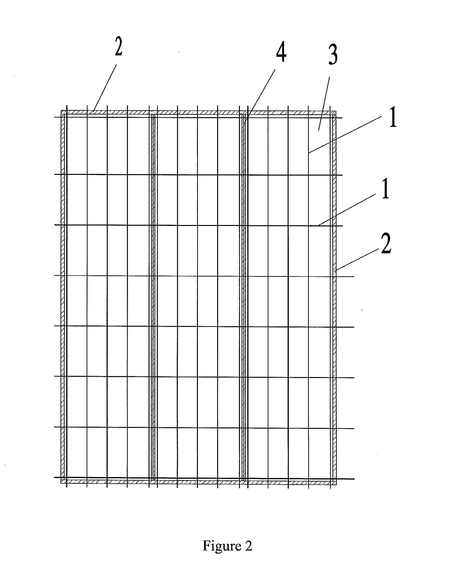
[0046]As shown in FIG. 1 to FIG. 3, a constructing method for a concrete cylinder of a construction steel bar of a high-rise steel structure specifically comprises:

[0047](1) Arranging a hydraulic mutual-type adhesive lifting scaffold creeping formwork system 100. The climbing formwork system comprises an attaching device, an H-shaped guide rail, a scaffold body, a large formwork supporting system, a large formwork moving trolley, a climbing mechanism, an electro-control hydraulic lifting system, anti-overturning and anti-falling devices and a safeguard system. It should be noted that, the scaffold body needs to be arranged to meet the construction requirement of every outer wall large formwork and to ensure that every outer wall large formwork has its corresponding and independent supporting system and climbing mechanism. The span of two adjacent positions is not more than 6 m when the climbing formwork system is arranged linearly, and is not greater than 5.4 m when the climbing for...


PUM


Abstract

A constructing method for a concrete cylinder of a construction steel bar of a high-rise steel structure adopts a constructing method of supporting inside and climbing outside. The outside of the cylinder adopts hydraulic mutual-climbing adhesive lifting scaffold creeping formwork system (100), and also has an outside wallboard mechanical formwork erection function and an outer frame protection function. For the inside of the cylinder, except that an appropriate structure is left for later processing according to a schedule requirement, beam walls all adopt a steel cylinder support to perform formwork erection, so as to greatly reduce the workload of repeatedly mounting/dismantling the scaffold and the formwork at a high place. The scaffold itself carries the formwork erection system, so formwork erection and formwork removal can be mechanized, thereby reducing the risk of formwork erection and formwork removal at a high place

Description

FIELD OF THE INVENTION[0001]The present invention belongs to the field of building construction, in particular to a constructing method for a concrete cylinder of a construction steel bar of a high-rise steel structure.BACKGROUND OF THE INVENTION[0002]The current common high-rise steel structure system is typically in the form of steel frame-core cylinder, namely: concrete filled steel tubular columns and steel beams constitute a structural frame, profiled steel sheet-concrete composite slabs, self-supporting slabs and reinforced concrete slabs together serve as a floor system, and a reinforced concrete core cylinder is used as a structural unit for enhancing the horizontal stiffness of a building. Deep research and summarization on a complete set of construction technologies of such structural systems can provide a powerful technical support for safe, high-quality and fast project construction.[0003]In conventional construction methods for a high-rise steel structure building reinf...

Claims


Application Information

Patent Timeline
IPC IPC(8): E04G11/28E04B2/84
CPCE04B2/84E04G11/28E04G5/046E04G2003/286
Inventor JIN, RUIZHAI, CHUANMINGCHANG, BOHU, QIANGWU, FEIPING, JINGHUIXU, WEI
Owner ZHEJIANG CONSTR ENG GRP CO LTD
Why Eureka
Try Eureka