Glass melting method and molten glass layer bubbling glass melting furnace

a glass melting furnace and glass melting technology, applied in the combustion process, charging furnace, lighting and heating equipment, etc., can solve the problems of fuel overconsumption and inability to control fuel combustion, and achieve the effect of minimizing working volume and high bulk heat load

Inactive Publication Date: 2014-10-30
FEDERALNOE GOSUDARSTVENNOE AVTONOMNOE OBRAZOVATELNOE UCHREZHDENIE VYSSHEGO PROFESSIONALNOGO OBRAZOVANIJA NATSIONALNYJ ISSLEDOVATELSKIJ TEKHNOLOGICHESKIJ UNIVT MISIS
View PDF20 Cites 10 Cited by
  • Summary
  • Abstract
  • Description
  • Claims
  • Application Information

AI Technical Summary

Benefits of technology

[0008]The technical objective of this invention is to provide a method and a furnace for producing molten glass with stabilized physical properties due to an increased phase boundary area, higher temperature in the glass furnace bath and intensified mixing as well as due to a higher output of the glass furnace.
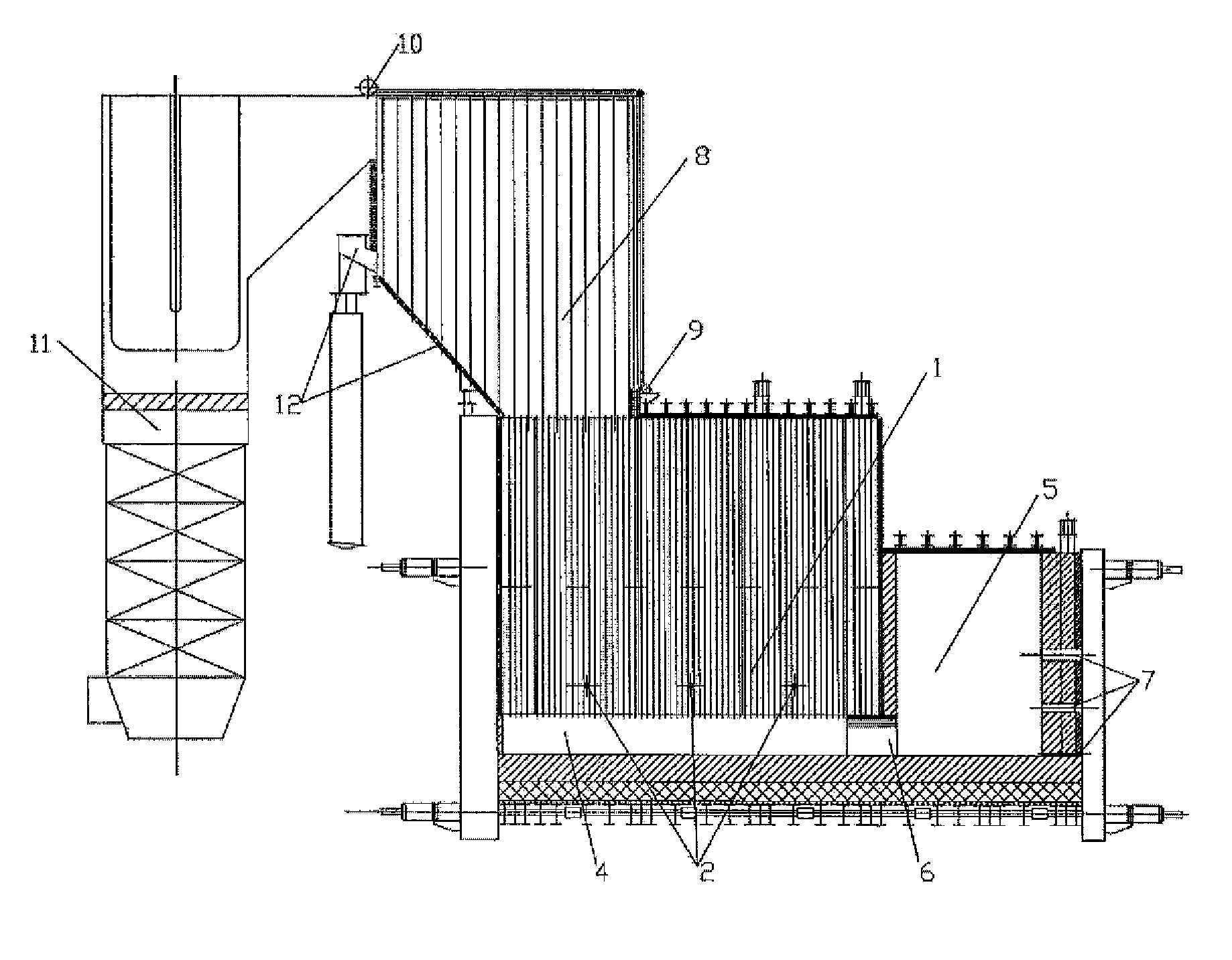
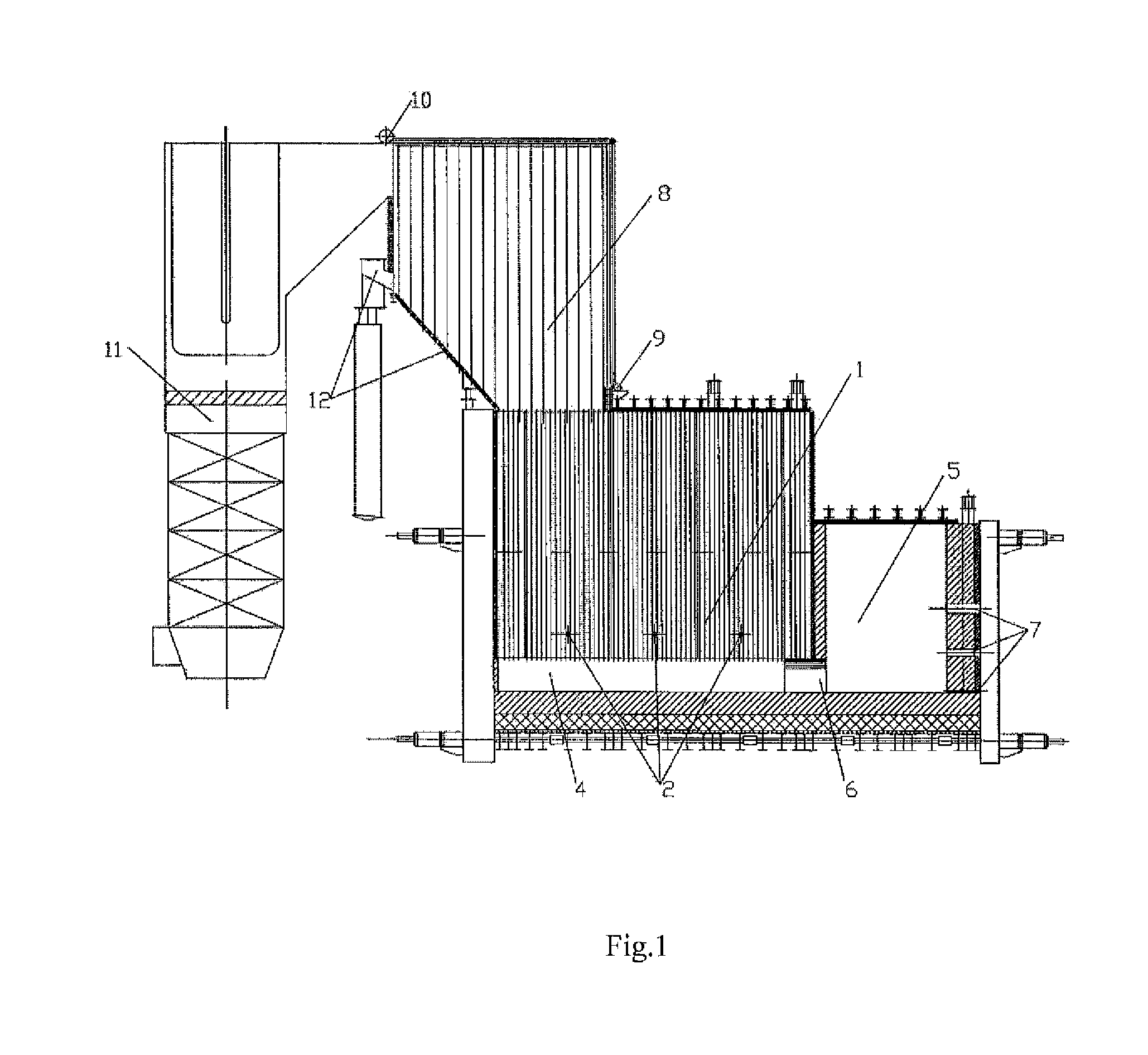
[0027]A fundamental feature of bubbling layer processes that provides for their high technical and economic performance is the maximally developed charge / molten glass phase boundary due to the elimination of charge piles from the glass melting bath surface, its loading to the mixed layer in the form of an uninterrupted flow, an extremely high bulk heat load and intense convective heat and mass exchange. Combined with the large phase boundary area, this determines the high output to raw material performance of bubbled layer furnaces.
[0029]The high bulk heat loads allow minimizing the working volume and furnace size for the preset output. Further requirement to the design of bubbled layer furnaces related to the high heat loads and intense bath mixing is the replacement of refractory lining in the furnace working space for water cooled metallic caissons with refractory packing. This replacement provides for durable and reliable furnace service life without walls overhauls. The large amounts of heat removed from the working chamber are delivered for heat recovery. High temperature off-gases released from the furnace are also delivered for heat recovery.

Problems solved by technology

Disadvantages of said known invention include burner installation inside or outside the melting chamber which does not allow controlling fuel combustion and hence maintaining the required combustion temperature and chemical composition.
Disadvantages of said known invention include submersible fuel combustion mode causing fuel overconsumption and not allowing one to control fuel combustion.

Method used


Image

  • Glass melting method and molten glass layer bubbling glass melting furnace
  • Glass melting method and molten glass layer bubbling glass melting furnace
  • Glass melting method and molten glass layer bubbling glass melting furnace

Examples


Embodiment Construction

[0032]The method of glass melting using the molten glass layer bubbling glass melting furnace is as follows.

[0033]The glass melting process can be divided into five stages: silicate formation, glass formation, homogenizing, degassing and cooling.

[0034]The silicate formation stage comprises melting of the fusible charge components and the completion of all the chemical reactions in the primary melt. at the end of this stage all the main oxides contained in the charge are bound with silica in the form of silicates. Silicate formation rate can be increased by earlier generation of the liquid phase in the charge. This is favored by increasing the charge / molten glass phase boundary area, high heat concentration in the unit volume of the media surrounding the melting charge, increasing the charge temperature in the melting zone (increasing charge temperature by 100-150° C. accelerates silicate formation twofold) and intensifying the mixing of the melting charge with its surrounding media....


PUM

PropertyMeasurementUnit
temperatureaaaaaaaaaa

Abstract

This invention relates to the continuous production of molten glass for further production of glassware and can be used for glass melting and obtaining glass semiproduct. The technical objective of this invention is to provide a method and a furnace for producing molten glass with stabilized physical properties due to an increased phase boundary area, higher temperature in the glass furnace bath and intensified mixing as well as due to a higher output of the glass furnace. Molten glass layer bubbling glass melting method comprising melting the glass layer in the first chamber of the furnace to the working level, further uninterrupted loading of large and small charge portions into the molten glass layer with simultaneous intense bubbling of the molten glass layer with high-temperature combustion products aiming at the formation of the maximum possible charge / molten glass phase boundary area and achieving a molten glass temperature of at least 1500° C., which conditions intensify the melting, silicate formation, vitrification and homogenizing processes, delivery of the chemically and thermally homogeneous molten glass produced by bubbling to the degassing and cooling section located under the bubbled molten glass layer, with an intense release from the molten glass layer of process gases that pass through the bubbled layer to the space above the layer where the process gases undergo primary cleaning and cooling, and the degassed molten glass is delivered to the further output section.

Description

FIELD OF INVENTION[0001]This invention relates to the continuous production of molten glass for further production of glassware and can be used for glass melting and obtaining glass semiproduct.BACKGROUND OF THE INVENTION[0002]Known are glass melting and degassing method and device (RU 2246454, publ. 20 Feb. 2005) comprising at least one melting chamber equipped with natural gas and oxidizer (e.g. air or oxygen) fueled burners arranged so that to direct the combustion product gases to the molten glass bulk below the level of glass loaded into said melting chamber. Said device delivers molten glass for degassing in the form of a thin layer. The degassing section is a steady state unit and comprises a molten glass discharge channel comprising a groove and a roof.[0003]Disadvantages of said known invention include burner installation inside or outside the melting chamber which does not allow controlling fuel combustion and hence maintaining the required combustion temperature and chemi...

Claims


Application Information

Patent Timeline
Patent Type & Authority Applications(United States)
IPC IPC(8): C03B5/193
CPCC03B5/193C03B3/026C03B5/2356C03B5/225C03B5/43C03B3/023C03B5/44F23C3/004F23D14/78F23D2214/00Y02P40/50
Inventor SBORSHIKOV, GLEB SEMENOVICHKLEGG, JURIY DGIMOVICHGRISHAEVA, SVETLANA VICTOROVNAKLEGG, DMITRIY JURIEVICH
Owner FEDERALNOE GOSUDARSTVENNOE AVTONOMNOE OBRAZOVATELNOE UCHREZHDENIE VYSSHEGO PROFESSIONALNOGO OBRAZOVANIJA NATSIONALNYJ ISSLEDOVATELSKIJ TEKHNOLOGICHESKIJ UNIVT MISIS
Why Eureka
Try Eureka