Micro-lens for high resolution microscopy

a micro-lens and high-resolution technology, applied in the field of ultra-high-resolution microscopy, can solve the problems of difficult operation of optical microscopes, difficult to view things smaller than 0.2 microns through standard optical microscopes, and the theoretical limit of optical microscope resolution of 200 nanometers, etc., to achieve high yield, easy operation in atmospheric conditions, and high reproducibility

Inactive Publication Date: 2014-11-13
SOUTHERN ILLINOIS UNIVERSITY
View PDF5 Cites 26 Cited by
  • Summary
  • Abstract
  • Description
  • Claims
  • Application Information

AI Technical Summary

Benefits of technology

[0012]An optical nanoscope is disclosed and claimed herein that can resolve features below 100 nm through the use of deliquescent-salt based microlenses. The nanoscopy is shown to break the diffraction limit and provides magnification between ×2 and ×6 in a conventional microscope using white light illumination. The method of achieving super-resolution is inexpensive and easy to operate in atmospheric conditions. Any conventional optical microscope can be easily converted into a super-resolution nanoscope by incorporating the proposed high-resolution microlens. The fabrication of the lens is extremely simple, highly reproducible with high yield, and an array of lenses can be self-assembled in a wet-lab without any need for clean-room facilities. With the imaging nanoscope as disclosed and claimed herein, the scientists will be able to probe under environmental conditions the biological particles, large biomolecules, and static and dynamic processes at / near cell surface at super-high resolution.

Problems solved by technology

Over time, such optical microscopes have become more and more complex using dozens of lenses and reflecting / refracting elements.
Today, such optical microscopes are considered to have a “theoretical limit” of resolution of about 200 nanometers—because of the resolution limitations of lenses and their index of refraction, the limited wavelengths of visible light, and limitations on the angular apertures of lenses.
Thus, things smaller than approximately 0.2 microns are not readily viewable through standard optical microscopes.
Even when viewing features at this lower resolution limit, some contrasts and color are often lost.
The diffractive light waves from objects are picked up by the objective and interfere with each other to produce contrastive images.
In general, a wide-field optical microscope cannot resolve two points that are <200 nm apart.
With fluids having higher refractive index (n), resolution (ds)can be further increased but usually these fluids are highly toxic or flammable in nature.
However, while electron microscopes can resolve features less than 0.2 microns, they typically cannot be used on living specimens.
Electron microscopes use very high energy electron beams which can be harmful to living specimens.
Also, to be viewed by an electron microscope, each specimen must be placed in a vacuum for viewing, as a gas would improperly scatter the electron beam, which vacuum would cause the death of a living specimen.
Further, electron microscopes are often quite expensive to purchase and maintain, and require special power sources and a stable building.
These techniques however face challenges of unavoidable losses or extreme fabrication finesse with multiple steps.
These methods have enhanced the imaging resolution, they also require complex / expensive instrumentation such as picoseconds lasers (STED and confocal microscopy), or demand special fluorophores (STROM / PALM) for enhancing the resolution.

Method used


Image

  • Micro-lens for high resolution microscopy
  • Micro-lens for high resolution microscopy
  • Micro-lens for high resolution microscopy

Examples


Embodiment Construction

[0063]According to the embodiment(s) of the present invention, various views are illustrated in FIGS. 1-30 of the drawings.

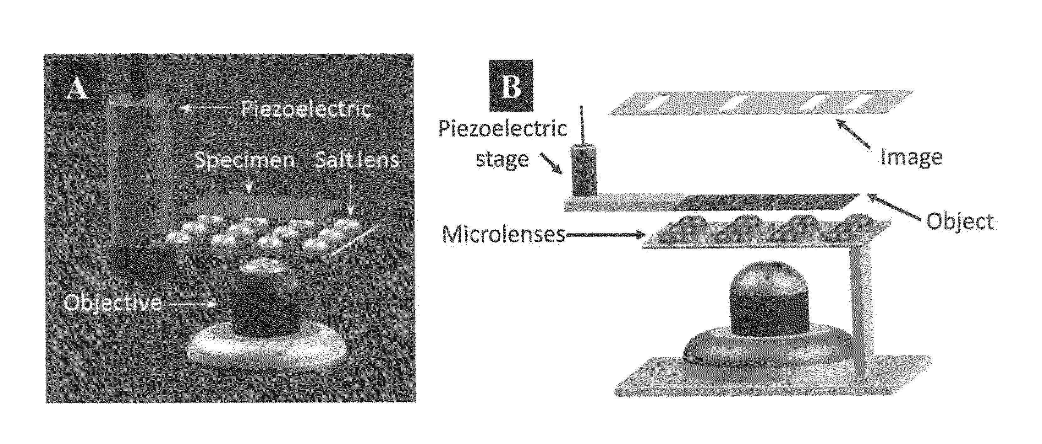
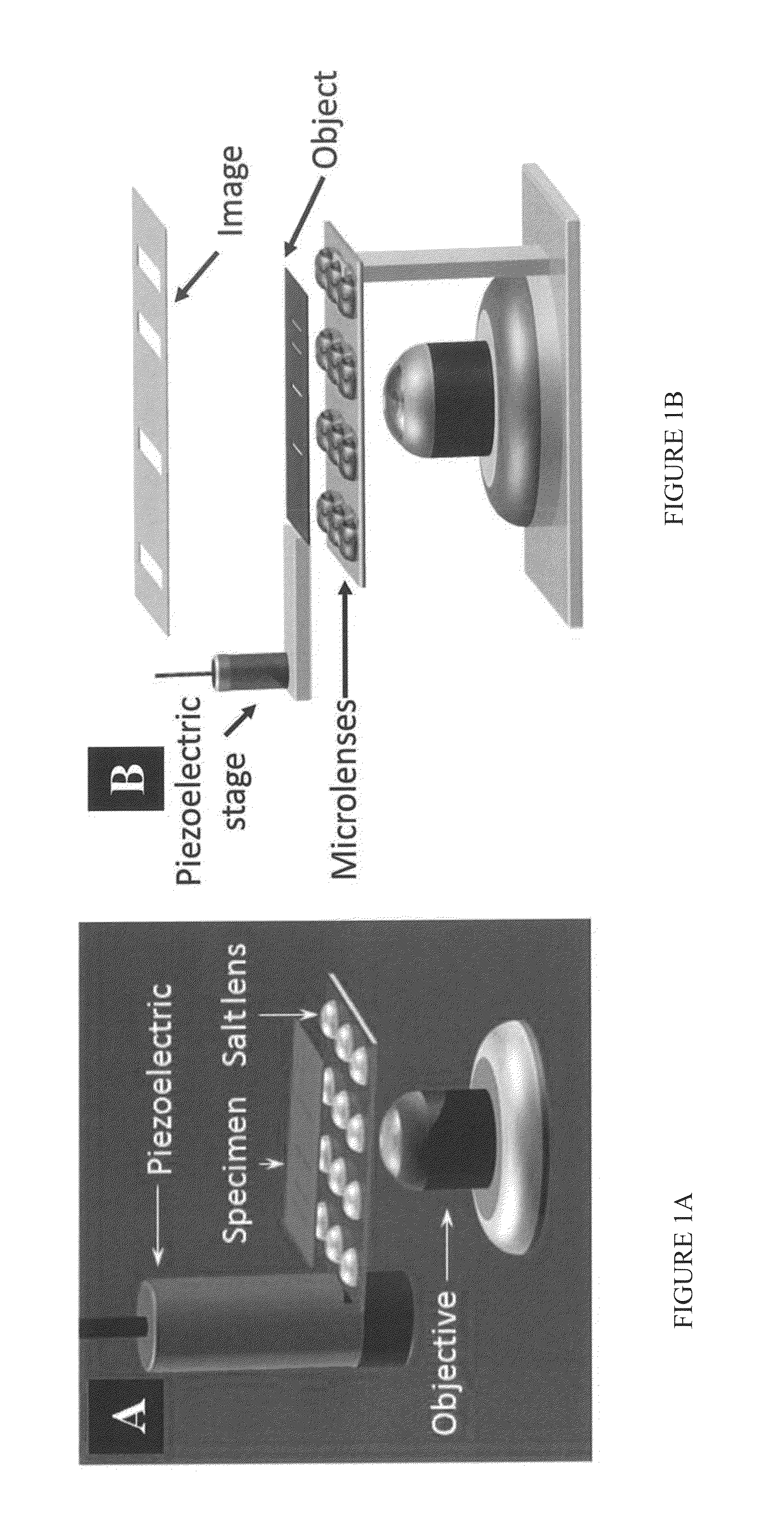
[0064]The technology as disclosed and claimed herein is a plano-convex deliquescent salt microlens (ML) based optical microscopy and scanning technique which can achieve resolution <100 nm using white light illumination without any significant modification to the conventional microscope. In the case of the glass ML, the ML is spherical constructed of glass microspheres. ML is operated in a very near approximate to the objective. The diffractive light from objects, including propagation waves and parts of evanescent waves, is picked up by ML and transferred into propagation or whisper gallery waves, forming the primary enlarged and super-resolved virtual image. Then the primary image is observed with microscope for a secondary magnification.

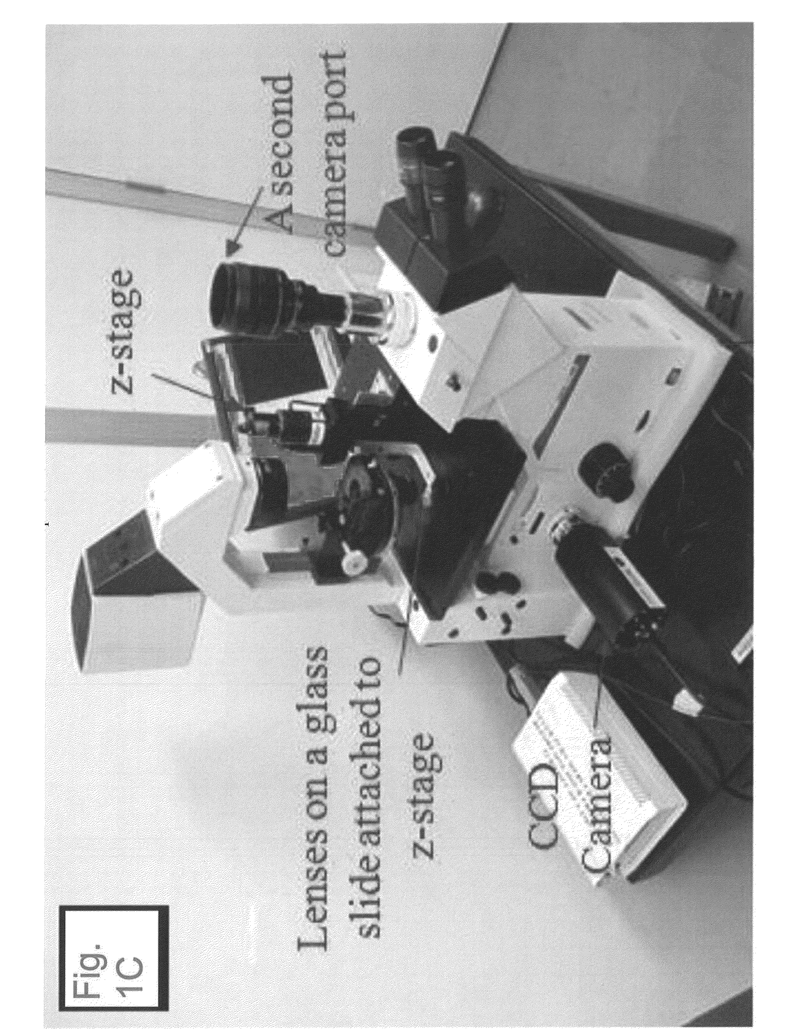
[0065]The ML-based nanoscope consists of a conventional microscope, a plano-convex ML, and a XYZ piezoelectric stage (FIGS. ...


PUM


Abstract

A method and apparatus for nanoscopy comprising a salt microlens. The microlens-based nanoscope comprises a conventional microscope, a microlens, and a XYZ piezoelectric stage is shown (SEE FIG. 1A). The microlens is mounted on a Z-stage and can be driven to accomplish the scanning. The specimen is placed above the microlens which is a plano-convex lens. The set up employed for the Salt Microlens for Ultra-high Resolution Imaging (SAMURI) can use a halogen-tungsten lamp with a dominant wavelength at 600 nm. A magnified virtual image of the specimen is obtained when the distance between microlens and specimen is less than the focal length of the microlens. The virtual image can then be magnified by the microscope and captured by eyes or a CCD camera.

Description

BACKGROUND OF INVENTION[0001]1. Field of Invention[0002]The present invention relates to ultra-high resolution microscopy for viewing microscopic and nanoscopic features. More specifically, the present invention relates to an optical design which provides high contrast and sharp images, providing for higher detail.[0003]2. Background Art[0004]Microscopes have been utilized by scientists and researchers for hundreds of years to observe items that are microscopic in size and not readily viewable by the human eye. From chemistry to the construction of computer chips to genetics to medical research, nearly every imaginable discipline has benefited from the ability to magnify items for viewing and observation.[0005]The oldest of microscopes were optical in nature, and were comprised of little more than a few lenses and a light source. These microscopes use the visible wavelengths of light to observe the microscopic object. Over time, such optical microscopes have become more and more com...

Claims


Application Information

Patent Timeline
Patent Type & Authority Applications(United States)
IPC IPC(8): G02B21/02G02B21/00G02B21/26
CPCG02B21/02G02B21/26G02B21/0044Y10S977/881B82Y35/00G02B1/02G02B3/0012G02B21/367G02B27/58
Inventor KOHLI, PUNITPRADEEP, RAMIAH RAJASEKARANZHOU, CHUANHONG
Owner SOUTHERN ILLINOIS UNIVERSITY
Why Eureka
Try Eureka