Vitrified super-abrasive-grain grindstone

a technology of super-abrasive grains and grinding stones, which is applied in the direction of gear teeth, manufacturing tools, manufacturing apparatus, etc., can solve the problems of residual stress caused to the shaft component, lowered hardness, and processing deformation, and achieves increased processing resistance, high knoop hardness, and enhanced abrasive grain dispersion

Active Publication Date: 2014-11-27
NORITAKE CO LTD
View PDF6 Cites 7 Cited by
  • Summary
  • Abstract
  • Description
  • Claims
  • Application Information

AI Technical Summary

Benefits of technology

The present invention relates to a vitrified superabrasive grain grinding stone, which includes a main abrasive grain and an auxiliary abrasive grain. The auxiliary abrasive grain has a smaller average grain diameter than the main abrasive grain, which improves the dispersibility of the main abrasive grain. The grinding stone also includes a diamond abrasive grain as an auxiliary abrasive grain, which has high thermal conductivity and helps absorb grinding heat and reduce residual stress. The auxiliary abrasive grain has optimal destructibility despite its high Knoop hardness, which increases the processing resistance but decreases the dressing performance. The contact angle of the auxiliary abrasive grain with the vitrified bond should be between 90 and 150° for optimal heat absorption and prevention of dropout. The auxiliary abrasive grain should ideally be contained at a volume ratio of 3 to 13 volume% to achieve optimal heat absorption and suppression of processing resistance and dressing performance. The vitrified bond should ideally contain 15 to 30 volume% to achieve the optimal grinding performance. The grinding stone can be made inexpensive by arranging the superabrasive grains in an area involved in grinding and using inorganic fillers for other portions.

Problems solved by technology

Conventionally, out of steel-made work materials, a shaft component such as a camshaft and a crankshaft as a main component of an automobile engine is subjected to a high-precision grinding process for enhancement of performance of the engine but there have been problems of processing deformation, lowered hardness, and residual stress caused to the shaft component as the work material by a grinding heat generated at the time of grinding.

Method used


Image

  • Vitrified super-abrasive-grain grindstone
  • Vitrified super-abrasive-grain grindstone
  • Vitrified super-abrasive-grain grindstone

Examples


embodiment

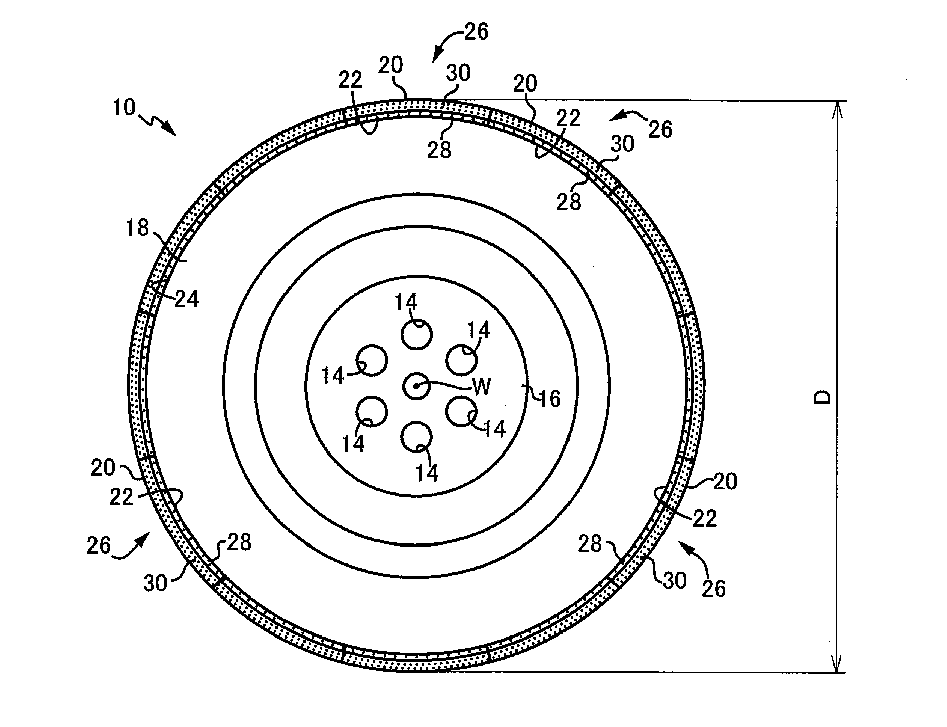
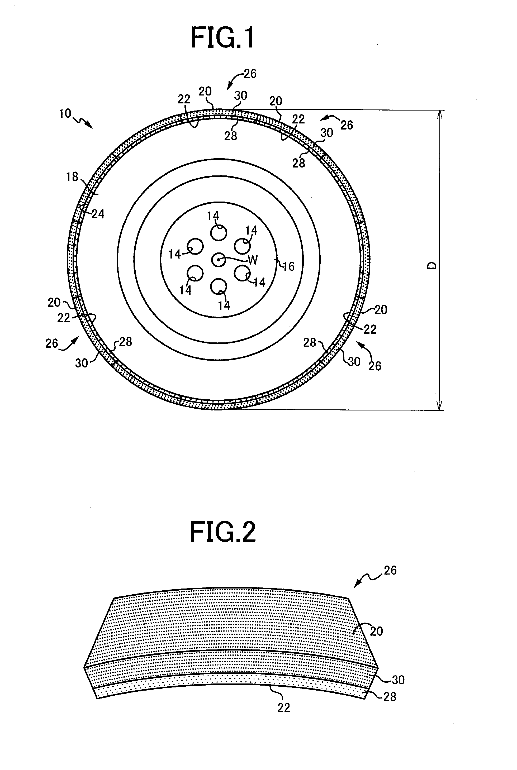
[0039]FIG. 1 is a front view of a superabrasive grain grinding wheel 10 manufactured through a manufacturing method according to an embodiment of the present invention. The superabrasive grain grinding wheel 10 has a core, namely, a base metal 18 that is of a shape of a disc made of metal such as, for example, carbon steel and aluminum alloy and has at its central part a mounting portion 16 having mounting holes 14 for mounting to a grinding device (e.g., a cylindrical grinding machine 12 to be described later) and plural pieces (12 pieces in this embodiment) of a vitrified grinding stone strip (segment grinding stone) 26 that is circular-arc-plate-shaped, curved along an arc having an axis of rotation W of the base metal 18 as its curvature center, has a grinding surface 20 on its outer peripheral surface and an adhesive surface 22 on an inner peripheral surface on a side opposite thereto, and has the adhesive surface 22 caused to stick tightly to an outer peripheral surface 24 of ...


PUM

PropertyMeasurementUnit
contact angleaaaaaaaaaa
temperatureaaaaaaaaaa
contact angleaaaaaaaaaa

Abstract

A vitrified superabrasive grain grinding stone includes superabrasive grains including a CBN abrasive grain as a main abrasive grain and a diamond abrasive grain as an auxiliary abrasive grain bonded together by use of a vitrified bond. The auxiliary abrasive grain has an average grain diameter equal to ½ to 1 / 10 of that of the main abrasive grain, and the auxiliary abrasive grain has a toughness value of 0.4 to 1 when that of the main abrasive grain is given as 1.

Description

TECHNICAL FIELD[0001]The present invention relates to a vitrified grinding stone formed by bonding superabrasive grains, using a vitrified bond and in particular, relates to a technology of suppressing occurrence of deformation, lowered hardness, and residual stress of a work material caused by a grinding heat.BACKGROUND ART[0002]A vitrified superabrasive grain grinding stone, because of bonding of superabrasive grains by melting down an inorganic vitrified bond at calcination temperature in the order of, for example, 500 to 1000° C., can have a high abrasive grain holding power, namely, a high adhesive power between the superabrasive grains and the vitrified bond, as compared with the case of using an organic resin bond. For example, in the case of CBN abrasive grain, it is considered that, since B element, and K or Na element, etc., within a catalyst, added during a synthesis process thereof, are present on a surface thereof, these elements react with the vitrified bond and their ...

Claims


Application Information

Patent Timeline
Patent Type & Authority Applications(United States)
IPC IPC(8): B24D3/14B24D5/06
CPCB24D5/06B24D3/14
Inventor MIZUNO, AKIHIROIMAI, NORIOYOSHIMURA, KOUICHIMISHIMA, TAKESHI
Owner NORITAKE CO LTD
Why Eureka
Try Eureka