Apparatus for controlling rotating machine based on output signal of resolver

a technology of resolver and output signal, which is applied in the direction of electronic commutators, motor/generator/converter stoppers, dynamo-electric converter control, etc., can solve the problems of increasing current flowing, reducing controllability of rotating machines, and reducing the accuracy of calculating the rotational angle outputted by rd converters. , to achieve the effect of reducing noise, avoiding degrading controllability of rotating machines, and reducing nois

Active Publication Date: 2014-12-11
DENSO CORP
View PDF1 Cites 28 Cited by
  • Summary
  • Abstract
  • Description
  • Claims
  • Application Information

AI Technical Summary

Benefits of technology

[0007]The embodiment provides a control apparatus in which the calculation accuracy of the rotational angle of a rotating machine can be prevented from being decreased.
[0008]As an first aspect of the embodiment, the control apparatus includes a signal output unit that outputs an excitation signal to a resolver used for detecting a rotational angle of the rotating machine; a demodulation unit that demodulates a signal related to the rotational angle based on a detection of a modulated signal where the excitation signal is amplitude-modulated in response to the rotational angle of the rotating machine and the excitation signal, and outputs a demodulated signal; a filter that eliminates higher harmonics in the demodulated signal outputted by the demodulation unit so as to output a calculated angle of the rotational angle; and an operating unit that controls a switching element included in a DC-AC conversion circuit to be ON and OFF based on the calculated angle of the rotational angle outputted by the filter, so as to control the rotating machine with an output voltage of the DC-AC conversion circuit supplied thereto.
[0012]Therefore, according to the first aspect of the embodiment and the second aspect of the embodiment, the frequency of the excitation signal and the switching frequency are set so as to have the error frequency to be within the cutoff region of the filter. Hence, even when noise is mixed to the excitation signal and the modulated wave so that noise is mixed to the demodulation signal, the filter can suppress influence of noise on the calculation accuracy of the rotational angle. As a result, the calculation accuracy of the rotational angle can be avoided from degrading and also, degrading controllability of the rotating machine can be avoided.

Problems solved by technology

In developing the motor control system, the inventors faced a problem that an accuracy of calculating the rotational angle outputted by the RD converter decreases when controlling the switching element in the DC-AC conversion circuit connected to the rotating machine to be ON and OFF thereby increasing the current flowing into the rotating machine.
Therefore, there is a concern that the controllability of the rotating machine is decreased when the calculation accuracy of the rotational angle decreases.
When the current flowing through the rotating machine becomes larger due to ON-OFF operation of the switching element, switching noise (electromagnetic waves) occurring due to the current flowing increases and mixes with the excitation signal or the modulated waves.
As a result, since the switching noise is mixed to the demodulation signal, an error occurs between the calculated value of the rotational angle outputted by the filter and the real rotational angle.

Method used


Image

  • Apparatus for controlling rotating machine based on output signal of resolver
  • Apparatus for controlling rotating machine based on output signal of resolver
  • Apparatus for controlling rotating machine based on output signal of resolver

Examples


first embodiment

[0036]With reference to the drawings, the first embodiment in which a control apparatus applied to a vehicle provided with a rotating machine as on-board main equipment (e.g., traction motor) is described as follows.

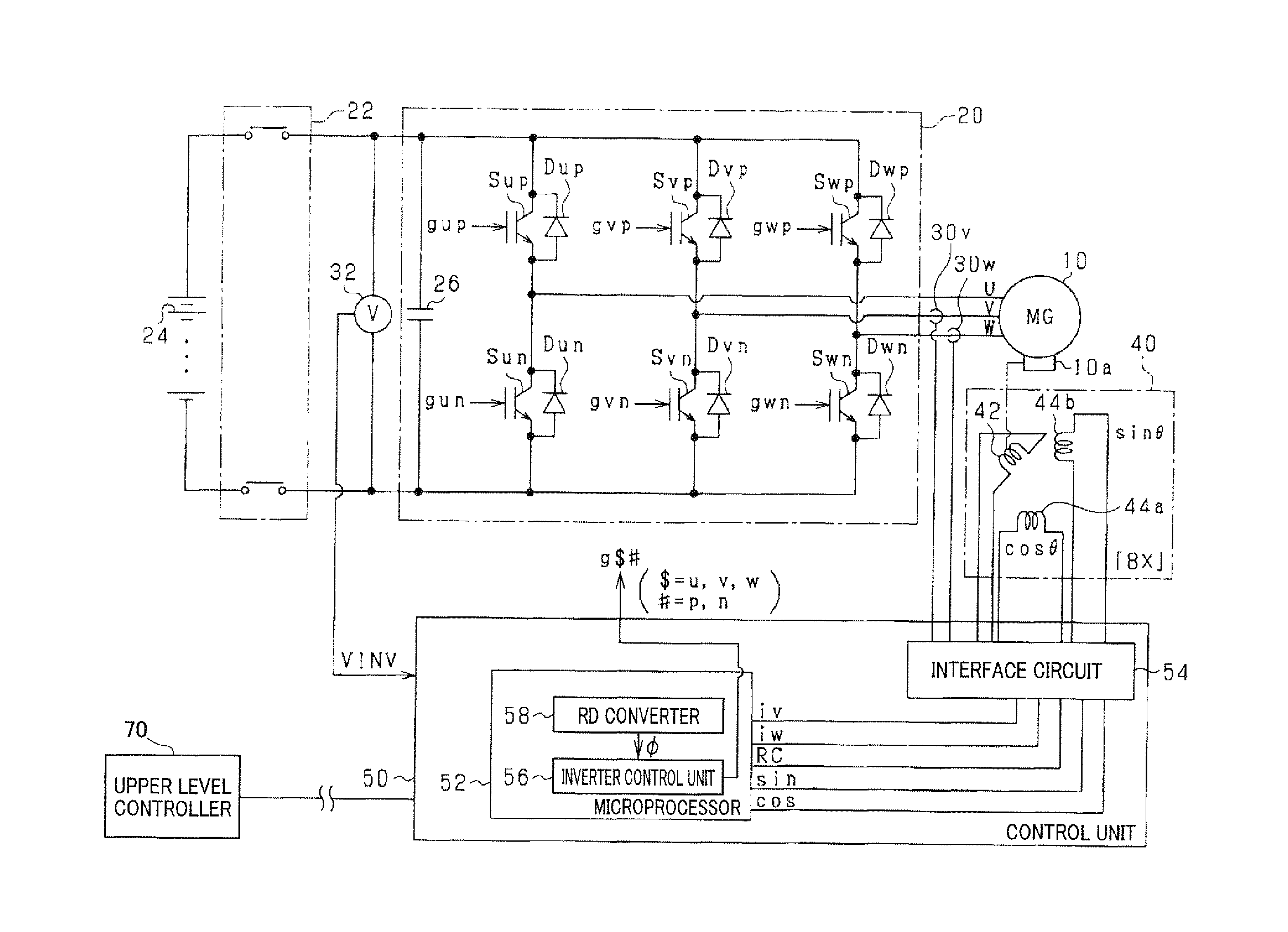
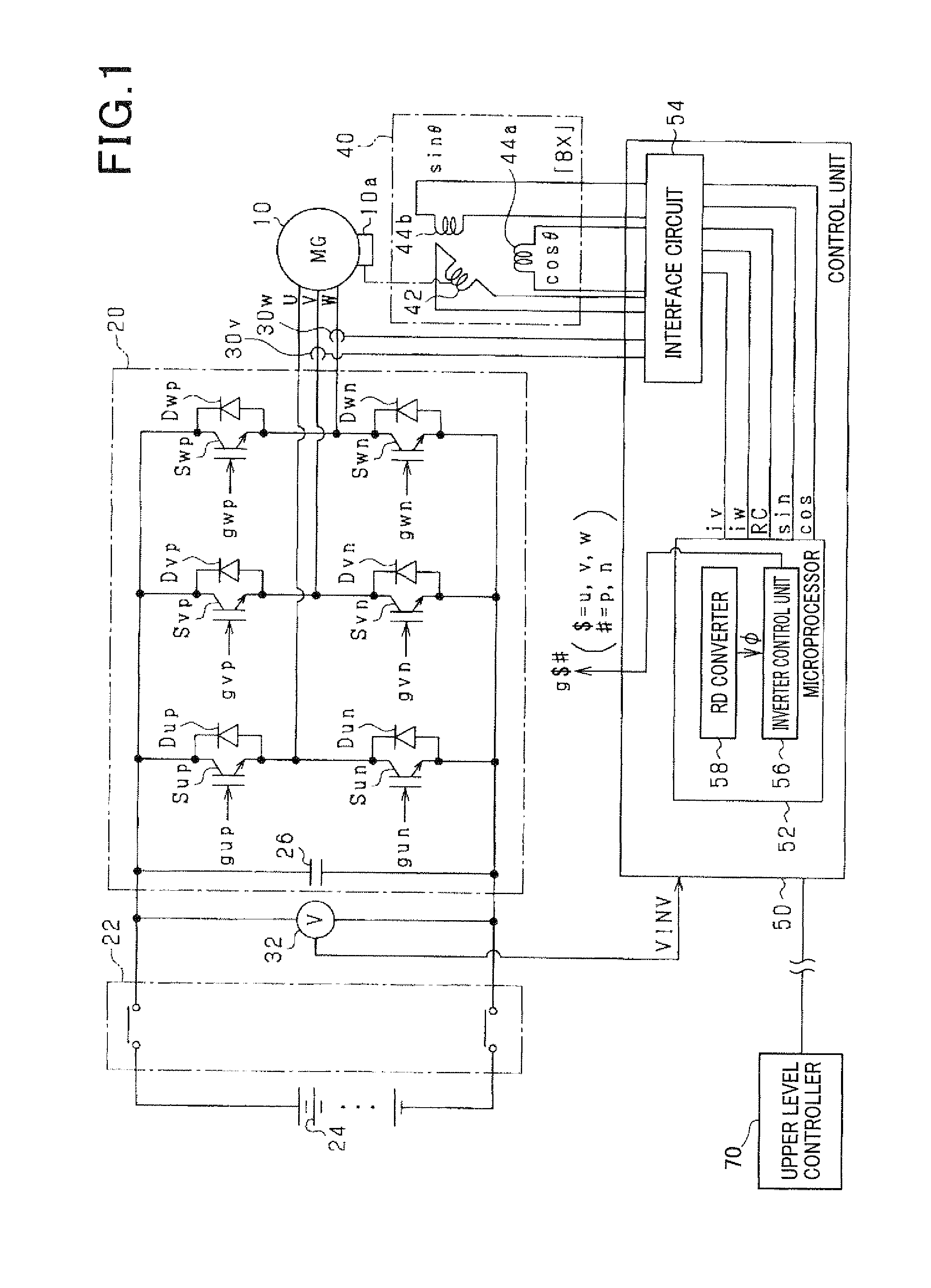
[0037]FIG. 1 is an overall configuration of a motor control system 1. As shown in FIG. 1, the motor generator 10 is a three-phase motor generator serving as on-board main equipment which is mechanically connected to a drive wheel (not shown) of the vehicle. According to the first embodiment, a permanent magnet synchronous motor is used for the motor generator 10 (i.e., interior permanent magnet synchronous motor: IPMSM).

[0038]The motor generator 10 is electrically connected to the high voltage battery 24 via an inverter 20 as a DC-AC conversion circuit and a main relay 22. The high voltage battery 24 is a rechargeable battery having a terminal voltage exceeding 100 volts (e.g., 288 volts). For example, a lithium-ion battery or a nickel-metal hydride battery can be used.

[...

second embodiment

[0091]With reference to the drawings, difference between the configuration of the second embodiment and the one of the first embodiment is mainly described as follows.

[0092]According to the second embodiment, the carrier frequency fc is set to be variable so as to eliminate the resolver error Er.

[0093]FIG. 15 is a block diagram showing a torque control according to the second embodiment. In FIG. 15, the same reference numbers are applied to components identical to that of the first embodiment.

[0094]As shown in FIG. 15, according to the second embodiment, instead of the asynchronous carrier generator 56e, a synchronous carrier generator 56h is included in the inverter control unit 56. The synchronous carrier generator 56h generates, based on the calculated angular velocity ω, a carrier signal tc such that one period of the calculated angle φ is equivalent to an integral multiple of a period of the carrier signal tc, and outputs the generated carrier signal tc. It is noted that the in...

third embodiment

[0108]With reference to the drawings, difference between the configuration of the third embodiment and the one of the second embodiment is mainly described as follows.

[0109]According to the third embodiment, the excitation frequency fref is used for the object frequency instead of the carrier frequency fc, so as to eliminate the resolver error Er.

[0110]In FIG. 19, a process of the variable frequency setting according to the third embodiment is described as follows. It is noted that this process is repeatedly executed by the microprocessor 52 at a predetermined period.

[0111]In this series of processes, at step S20, the control determines whether or not a logical OR operation between a condition that the torque command Trq* exceeds the torque control value Ty and a condition that the calculated angular velocity ω is less than the velocity threshold ωth is true. This process is to determine whether or not the excitation frequency should be changed variably. The meaning of this process ...


PUM


Abstract

A control apparatus controlling a rotating machine includes a signal output unit that outputs an excitation signal to a resolver used for detecting a rotational angle of the rotating machine; a demodulation unit that demodulate a signal related to the rotational angle based on a detection of a modulated signal and the excitation signal so as to output a demodulated signal; a filter that eliminates higher harmonics in the demodulated signal outputted by the demodulation unit so as to output a calculated angle of the rotational angle; and an operating unit that controls a switching element included in a DC-AC conversion circuit to be ON and OFF based on the calculated angle of the rotational angle outputted by the filter, so as to control the rotating machine with an output voltage of the DC-AC conversion circuit supplied to the rotating machine.

Description

CROSS REFERENCE TO RELATED APPLICATION[0001]This application is based on and claims the benefit of priority from earlier Japanese Patent Application No. 2013-118912 filed on Jun. 5, 2013 the description of which is incorporated herein by reference.BACKGROUND[0002]1. (Technical Field)[0003]The present disclosure relates to an apparatus for controlling a rotating machine based on an output signal of a resolver.[0004]2. (Description of the Related Art)[0005]Conventionally, a motor control system provided with a resolver and a resolver digital converter (hereinafter is referred to RD converter) is known. In the motor control system, a control apparatus controls a rotating machine based on the output signal of the resolver. Specifically, the control apparatus controls, based on the output signal of the resolver, a switching element included in the DC (direct current)-AC (alternating current) conversion circuit which is electrically connected to the rotating machine. For example, a Japane...

Claims


Application Information

Patent Timeline
Patent Type & Authority Applications(United States)
IPC IPC(8): H02P6/16H02P27/02H02P6/06H02P6/08H02P6/28H02P21/00H02P21/22H02P27/08
CPCH02P6/16H02P29/50
Inventor MIYACHI, JYUNJIMAEBARA, TSUNEO
Owner DENSO CORP
Why Eureka
Try Eureka