Estimation and display for vector doppler imaging using plane wave transmissions

a plane wave transmission and doppler imaging technology, applied in the field of ultrasonic imaging, can solve the problems of more extensive processing capabilities, more expensive ultrasound systems, and too high equipment costs for significant adoption, and achieve the effects of improving accuracy, allowing flexibility in balancing frame rate and sensitivity

Active Publication Date: 2014-12-18
VERASONICS
View PDF9 Cites 45 Cited by
  • Summary
  • Abstract
  • Description
  • Claims
  • Application Information

AI Technical Summary

Benefits of technology

[0023]The gradient-based method allows augmentation of the observation in the estimation model, with conjugate-lag product samples (autocorrelation summands)—in addition to the zero lag (IQ magnitude case)—at lags of higher numbers, and as well as instantaneous Doppler-derived velocity estimates. This augmentation provides improved precision with a trade-off against accuracy.
[0024]Compared to the multi-angle Doppler-based process disclosed within, the gradient-based approach allows for a l

Problems solved by technology

Unfortunately, there are still many applications for ultrasound systems where the equipment costs are too high for significant adoption.
These performance capabilities are found only on the more expensive ultrasound systems, which have more extensive processing capabilities.
Unfortunately, the low manufacturing volumes of ultrasound systems results in substantial overhead and fixed costs for these unique circuits, and thus the transition to digital signal processing has not significantly reduced system cost.
Color Flow Doppler can provide approximate mean flow velocities in the region of interest, but accuracy is limited due to the short acquisition sequences needed to maintain reasonable frame rates.
Using a small ROI can improve frame rates, but may limit the assessment of flow abnormalities.
In general, high quality Doppler imaging is more technic

Method used


Image

  • Estimation and display for vector doppler imaging using plane wave transmissions
  • Estimation and display for vector doppler imaging using plane wave transmissions
  • Estimation and display for vector doppler imaging using plane wave transmissions

Examples


Embodiment Construction

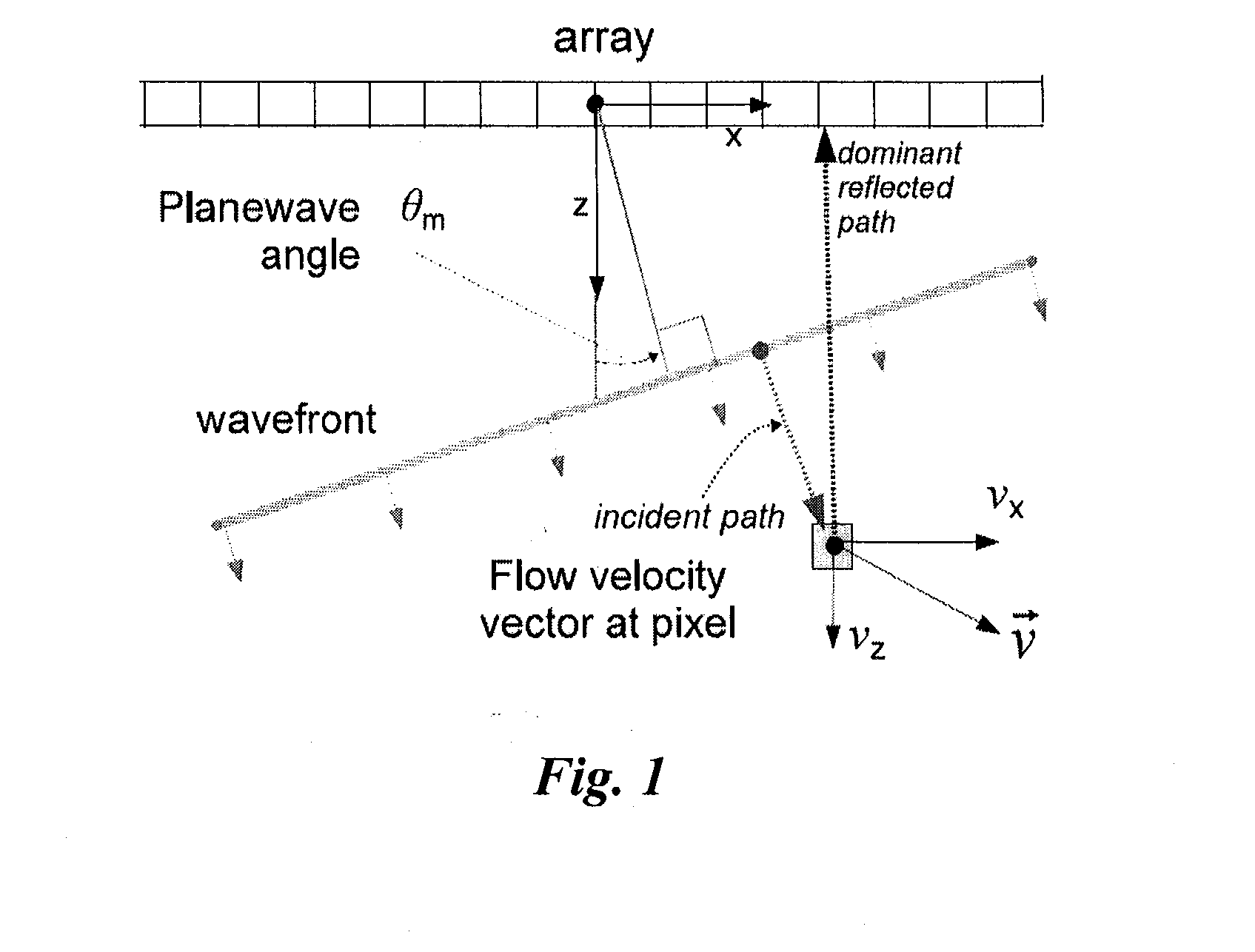
[0042]In the multi-angle Doppler-based method of vector flow estimation, a PWT measurement model is partitioned into nonlinear and linear components in a way that simplifies vector velocity computation. Each pixel's velocity vector predicts the IQ measurements at diverse angles of PWT ensembles through a nonlinear model, which we linearize by transforming with conventional CDI processing (clutter filtering and Kasai autocorrelation) to a set of Doppler frequencies. Velocity vector estimation then simplifies as the solution to a small linear weighted least squares (WLS) problem, conditioned on a hypothesized measurement bias due to aliasing. Weights derived from CDI autocorrelation lag variances account for clutter filtering effects. The nonlinearity of the original problem is thus reduced to a discrete search over a finite number of known aliasing bias vectors. Further, the WLS estimator covariance provides information used to qualify pixels.

[0043]In the gradient-based vector blood ...


PUM


Abstract

Vector Doppler Imaging (VDI) improves on conventional Color Doppler Imaging (CDI) by giving speed and direction of blood flow at each pixel of a display generated by a computing system. Multiple angles of Plane wave transmissions (PWT) via an ultrasound transducer conveniently give projected Doppler measurements over a wide field of view, providing enough angular diversity to identify velocity vectors in a short time window while capturing transitory flow dynamics. A fast, aliasing-resistant velocity vector estimator for PWT is presented, and VDI imaging of a carotid artery with a 5 MHz linear array is shown using a novel synthetic particle flow visualization method.

Description

BACKGROUND[0001]1. Technical Field[0002]The present disclosure pertains to ultrasound imaging and, more particularly, to an ultrasound imaging system utilizing velocity vector estimation for generation of a vector Doppler color image in which a synthetic particle flow visualization method is employed.[0003]2. Description of the Related Art[0004]Ultrasound Imaging has developed into an effective tool for diagnosing a wide variety of disease states and conditions. The market for ultrasound equipment has seen steady growth over the years, fueled by improvements in image quality and the capability to differentiate various types of tissue. Unfortunately, there are still many applications for ultrasound systems where the equipment costs are too high for significant adoption. Examples are application areas such as breast cancer detection, prostate imaging, musculoskeletal imaging, and interventional radiology. In these areas and others, the diagnostic efficacy of ultrasound imaging depends...

Claims


Application Information

Patent Timeline
IPC IPC(8): A61B8/08A61B8/06
CPCA61B8/488A61B8/5223A61B8/5207A61B8/06G01S15/8977G01S15/8984G01S15/8995G01F1/663G01S15/8979A61B8/14A61B8/4483A61B8/463A61B8/5269
Inventor FLYNN, JOHNDAIGLE, RONALD ELVIN
Owner VERASONICS
Why Eureka
Try Eureka