Prepreg for manufacturing composite materials

Active Publication Date: 2014-12-25
GURIT (UK) LTD
View PDF2 Cites 29 Cited by
  • Summary
  • Abstract
  • Description
  • Claims
  • Application Information

AI Technical Summary

Benefits of technology

[0082]In some embodiments the melting point of the toughening particle is below the cure temperature of the matrix resin material of the prepreg in order to improve particle dispersion, and hence toughening.
[0083]The toughening parameters GIC and GIIC of composite materials have been found to increase by 50-200% by using the toughening additive power coating in accordance with the invention, without reducing other mechanical properties.
[0084]In this aspect of the invention it is the objective to provide a toughened interleave region to increase fracture toughness properties. Traditionally, thermoplastics or elastomers are dispersed throughout the thermoset resin matrix. During cure of the laminate, these form separate rubber phases within the resin matrix. The

Problems solved by technology

However, one particular problem with fully impregnated prepregs is that when a stack of such prepregs is formed, air can be trapped between the adjacent prepreg plies, with the result that in the final cured resin matrix of the fibre reinforced composite material inter-ply voids can exist.
The presence of these voids can significantly reduce the mechanical properties of the composite material.
The tackiness of the resin surfaces of the adjacent prepreg layers increases the possibility of air being trapped between the plies at the prepreg interfaces.
In comparison to stitched, multiaxial and woven materials, multiple layers of unidirectional fibres will nest and pack efficiently leaving limited free volume space, which reduces air and resin permeability.
Carbon fibres typically are smaller in diameter (7 micron) than glass fibres (17-24 micron) and therefore such carbon fibre stacks are harder to process reliably as they are inherently less permeable to air and resin.
The fibre support structure causes waviness of the fibres, reducing the final load carrying capacity, especially in compression.
Thick sections of carbon fibre have proved difficult to infuse reliably with the VARTM method due to the low permeability of the reinforcement.
These materials do not provide laminates with very low void levels, high levels of fibre alignment and

Method used


Image

  • Prepreg for manufacturing composite materials
  • Prepreg for manufacturing composite materials
  • Prepreg for manufacturing composite materials

Examples


example 1

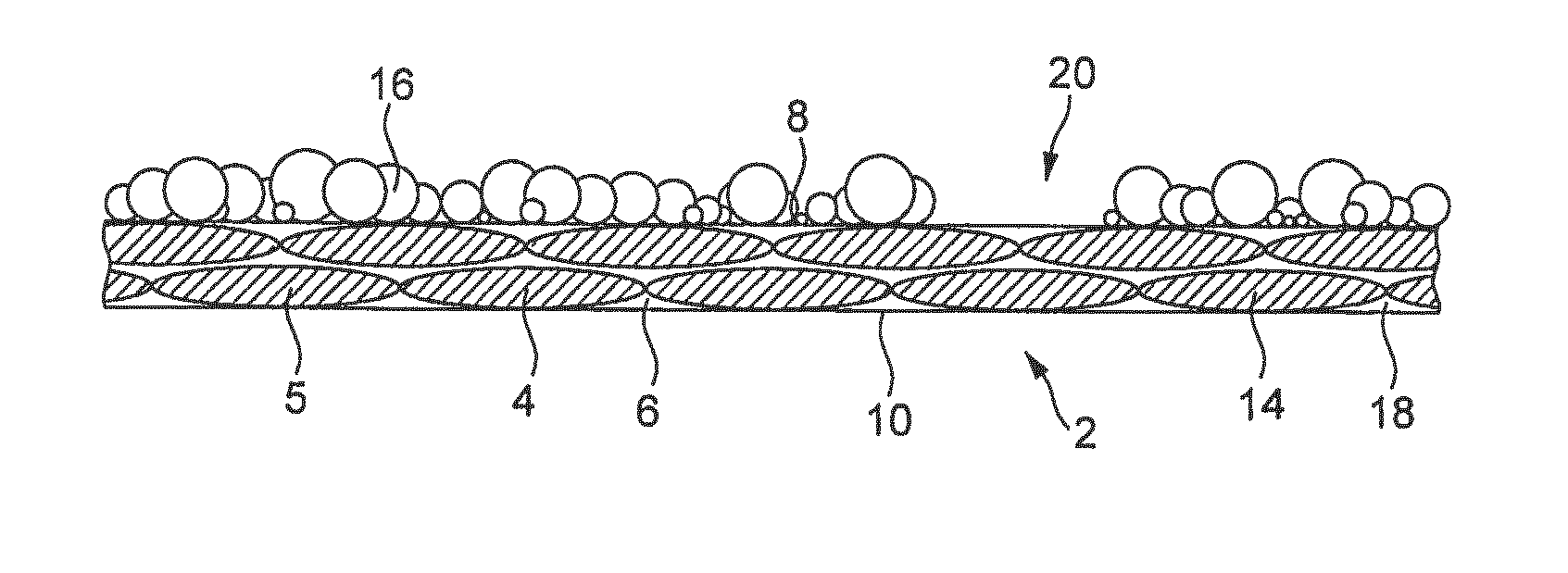
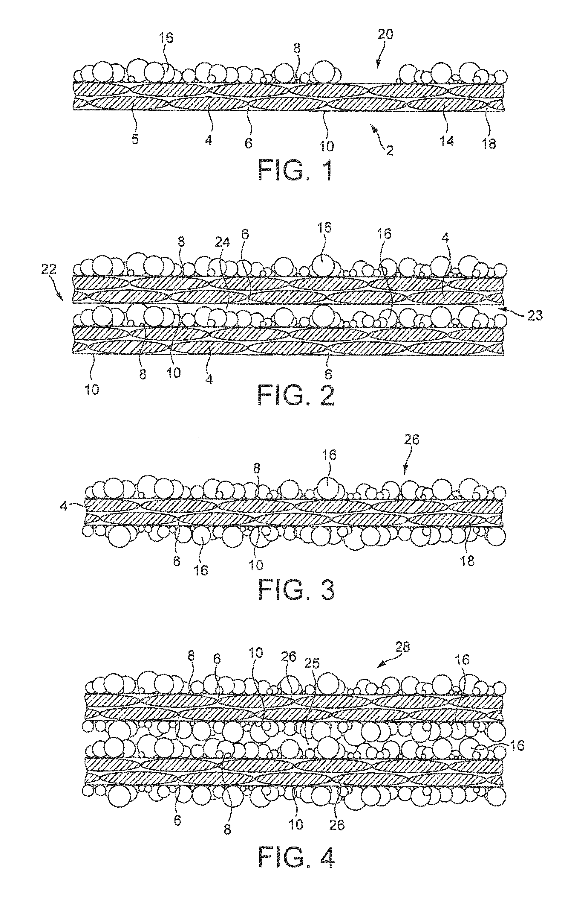
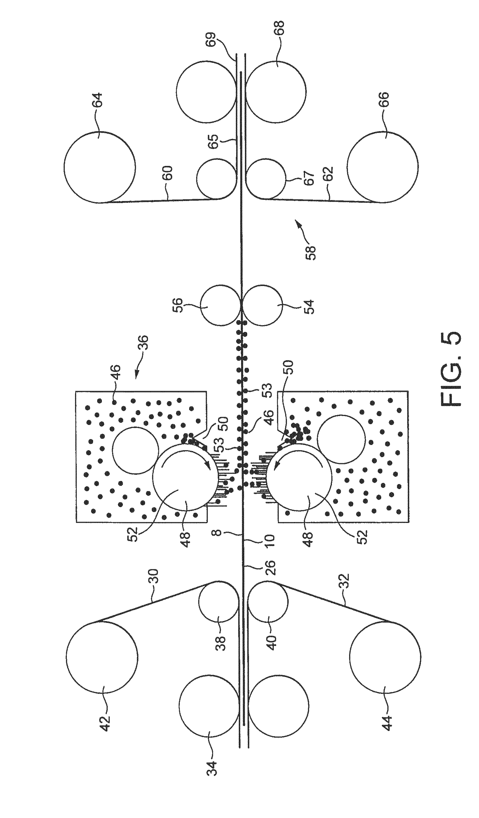
[0159]A fully impregnated carbon fibre prepreg having an epoxy matrix resin was manufactured. The carbon fibres were unidirectional (UD) fibres having a fibre weight of 600 grams per square metre. The prepreg had a resin content of 35% by weight, based on the weight of the prepreg. The epoxy resin was a commercially available prepreg resin, in particular a diglycidyl ether of bisphenol A (DGEBA) epoxy prepreg resin incorporating a dicyandiamide / urea curing system. The resin had low tack (Tack rating QC-2 at 20° C.). The resin is available in commerce from Gurit (UK) Limited, Newport, UK, under the trade name Gurit SPX17551. The epoxy matrix resin, designated as resin A, had the viscosity / temperature profile as shown in FIG. 9.

[0160]The tack rating is as follows: ZT—Zero Tack; QC-0 Does not stick at all. Surface dry to the touch; LT Low Tack—gloved finger easily removed after touching surface; QC-1 Sticks only with firm pressure. Parts very easily. Surface quite dry to the touch; QC-...

example 2

[0175]Example 2 produced a powder coated prepreg in a manner similar to Example 1. However, the prepreg matrix resin was different, and the amount of powder applied to the prepreg surfaces was modified.

[0176]The epoxy matrix resin of the prepreg was a commercially available prepreg resin, in particular a diglycidyl ether of bisphenol A (DGEBA) epoxy prepreg resin incorporating a dicyandiamide / urea curing system available in commerce from Gurit (UK) Limited, Newport, UK, under the trade name Gurit WE91-2. The resin had mid tack (Tack rating QC-3 at 22° C.). The epoxy matrix resin, designated as resin B, had the viscosity / temperature profile as shown in FIG. 9.

[0177]The powder coating was 7 grams per square metre on the each surface of the prepreg. The resulting prepreg was substantially coated and free from resin tack.

[0178]The powder coated prepreg was then tested to determine its drape limit, tack limit, void limit and temperature range for processing.

[0179]The results are shown in...

examples 3 to 8

[0202]Examples 3 to 8 each produced a powder coated prepreg in a manner similar to Example 2. However, the prepreg matrix resin was different, the powder particle size was different, the amount of powder applied to the prepreg surfaces was modified, and the powder application process and conditions were modified.

[0203]The prepreg was the same as that of Example 2, incorporating the epoxy matrix resin designated as resin B.

[0204]The production of a powder coating was as follows. A DGEBA epoxy resin having an epoxy equivalent weight of 840-900 gmol−1 (measured according to EN ISO 3001) and a softening point of 110-112° C. (measured according to EN ISO 4625) was provided. The resin is available in commerce from Nan Ya Plastics Corporation of Taipei, Taiwan under the trade name NPES 904H. The resin was ground to give a powder and then calibrated into a series of set particle size ranges using a series of woven wire mesh sieves conforming to IOS 3310.

[0205]Example 3 had a particle size o...


PUM

PropertyMeasurementUnit
Temperatureaaaaaaaaaa

Abstract

A prepreg for manufacturing a fibre-reinforced composite material, the prepreg comprising a body comprising a layer of fibrous reinforcement impregnated with a matrix resin material, and a powder coating layer of resin material on at least one major surface of the body and adhered to the matrix resin material

Description

FIELD OF THE INVENTION[0001]The present invention relates to a prepreg for manufacturing a fibre-reinforced composite material and to a method of manufacturing such prepreg. The present invention further relates to the use of such a prepreg for manufacturing a fibre-reinforced composite material.BACKGROUND[0002]It has been known for many years in the field of fibre-reinforced composite materials to provide a prepreg which comprises a layer of fibrous reinforcement impregnated with a structural polymer resin. The amount of structural polymer resin is carefully matched with the amount of fibrous reinforcement. Accordingly, the prepreg may be used in a method for forming a fibre-reinforced composite material, in which a multilayer stack of prepregs is provided having a desired shape and configuration, and then is subjected to heating so that the structural polymer resin melts and then solidifies to form a single unified resin matrix in which the fibrous reinforcement is disposed in the...

Claims


Application Information

Patent Timeline
IPC IPC(8): B32B37/26B32B38/00C08J5/24B32B37/10
CPCB32B37/26B32B37/1018C08J2363/00C08J5/24B32B2038/0076B32B38/00C08J5/04Y10T428/24405Y10T428/24893Y10T428/24372C08J5/243C08J5/249B05D1/06B32B5/16B05D2504/00B05D2201/00B32B2264/0214B32B2305/20B32B2305/076B32B2260/046B32B2260/021B32B2255/26B32B2255/02B32B2307/724B32B2363/00
Inventor CREASER, BENJAMIN EDWARDSPENCER, PAUL JOHN
Owner GURIT (UK) LTD
Why Eureka
Try Eureka