Very thin dielectrics for high permittivity and very low leakage capacitors and energy storing devices

a dielectric and capacitor technology, applied in the field of very thin dielectrics, can solve the problems of difficult and dangerous use of liquid form, undesirable conductivity of polar salts, and difficulty in using liquid form, so as to avoid electrical breakdown, enhance the permittivity of one or more layers, and achieve high permittivity

Active Publication Date: 2015-01-01
CARVER SCI INC
View PDF8 Cites 30 Cited by
  • Summary
  • Abstract
  • Description
  • Claims
  • Application Information

AI Technical Summary

Benefits of technology

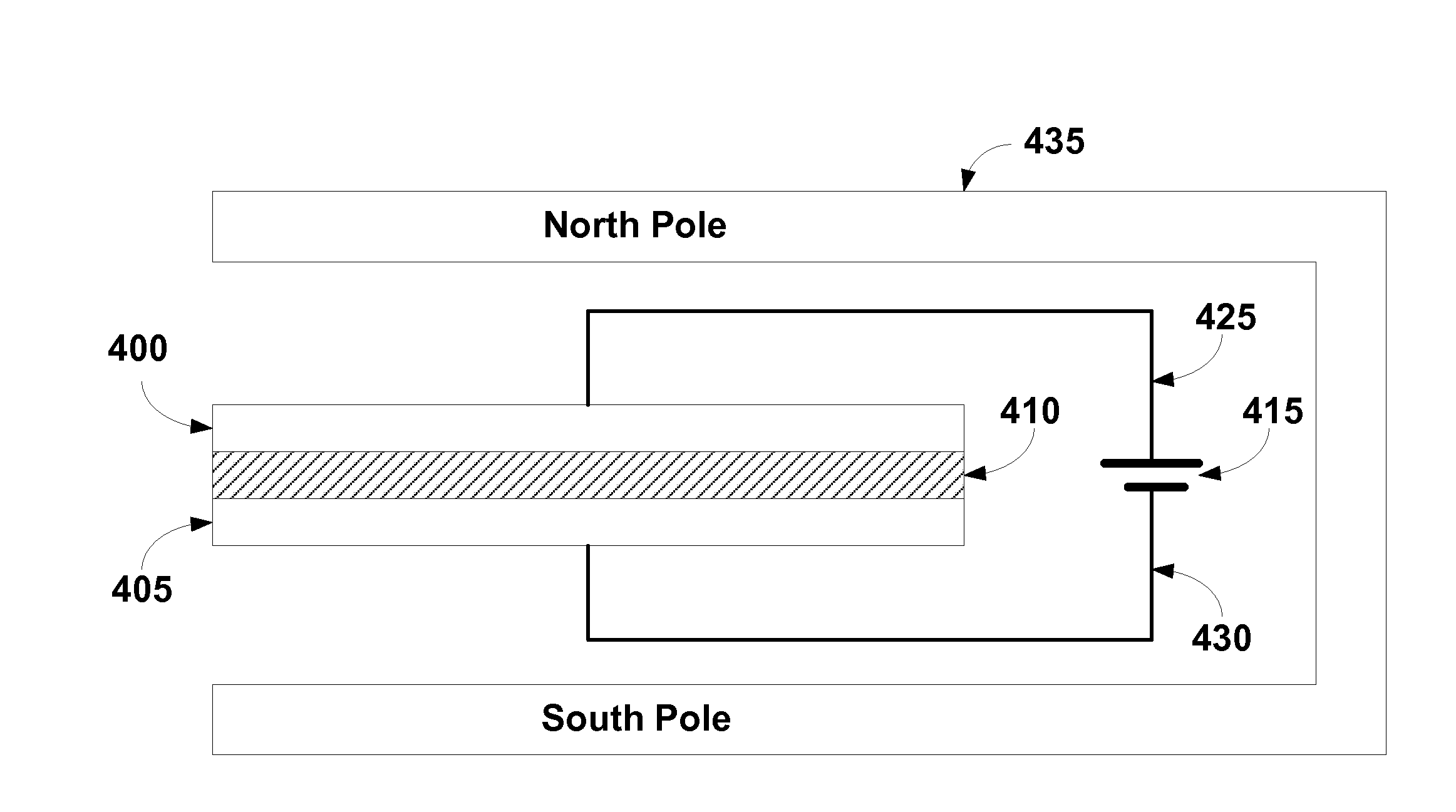
[0029]In another embodiment, a layered dielectric is created with a first dielectric film layered on a different second dielectric film, each of which is composed of a primarily insulative film material and / or a high permittivity material. The film layers are sandwiched between and in contact with opposing first and second electrodes. Either during or after formation of the layers, permittivity of one or more layers is enhanced by one or more of: immersion in an electric field and / or magnetic field, and / or introducing a reductant into the film material.
[0030]Recognizing that perfect insulators do not exist, as used herein, an “insulative” material is a material that is primarily insulative. A primarily insulative material has a threshold breakdown field that exceeds the electric field applied across the substance during normal use as a capacitor, thus avoiding electrical breakdown during normal use.
[0031]In yet another embodiment, a mixed dielectric is created from an insulative film material and / or a high permittivity film material that exhibits a high permittivity. Again, The film is sandwiched between and in contact with opposing first and second electrodes. Either during or after formation of the film, permittivity is enhanced by one or more of: immersion in an electric field and / or magnetic field, and / or introducing a reductant into the film material.

Problems solved by technology

In these cases their liquid form is difficult to use and / or toxic or corrosive.
This makes their utility difficult and dangerous.
Often, polar salts display undesirable conductivity when they are slightly impure and / or exposed to atmospheric conditions with humidity.
These materials are difficult to use due to their crystalline nature.

Method used


Image

  • Very thin dielectrics for high permittivity and very low leakage capacitors and energy storing devices
  • Very thin dielectrics for high permittivity and very low leakage capacitors and energy storing devices
  • Very thin dielectrics for high permittivity and very low leakage capacitors and energy storing devices

Examples


Embodiment Construction

[0043]Methods of forming high permittivity low leakage capacitors and energy storing devices are described herein. In one or more embodiments, the methods, materials and devices described in the present disclosure reduce the difficulties associated with the manufacture of high permittivity materials, decrease the difficulty of incorporation of these materials into devices, increase the performance of the materials, and show a method whereby the materials performance may be enhanced through the use of external fields used during manufacture.

[0044]When considering capacitors and their relationships to energy, to determine the work that must be done to charge a capacitor (i.e. the potential energy=E), the work performed is equal to the potential energy stored in the capacitor. The work performed to transfer a given amount of charge into a given capacitance is given by the following formula:

W=q2C·2Eq.3[0045]where the relationship between capacitance and charge is:

q=C·V [0046]where[0047]...


PUM

PropertyMeasurementUnit
electric fieldaaaaaaaaaa
relative permittivityaaaaaaaaaa
dielectricaaaaaaaaaa

Abstract

Methods are disclosed for creating extremely high permittivity dielectric materials for use in capacitors and energy storage devices. High permittivity materials suspended in an organic non-conductive media matrix with enhanced properties and methods for making the same are disclosed. Organic polymers, shellac, silicone oil, and/or zein formulations are utilized to produce thin film low conductivity dielectric coatings. Transition metal salts as salt or oxide matrices are formed at low temperatures utilizing mild reducing agents.

Description

RELATED APPLICATIONS[0001]This application is a continuation-in-part and claims the benefit of priority of U.S. Nonprovisional application Ser. No. 13 / 426,440 filed Mar. 21, 2012, which is a nonprovisional of and claims the benefit of priority of U.S. Provisional Patent Application 61 / 466,058, filed Mar. 22, 2011, and a continuation in part of U.S. Nonprovisional application Ser. No. 13 / 853,712, filed Mar. 29, 2013, which is a continuation in part of U.S. Nonprovisional application Ser. No. 13 / 671,546 filed Nov. 7, 2012, and a Continuation-in-part of U.S. Nonprovisional application Ser. No. 13 / 599,996 filed Aug. 30, 2012, now patented as U.S. Pat. No. 8,633,289, and a Continuation-in-part of U.S. Nonprovisional application Ser. No. 12 / 245,665 filed Oct. 3, 2008, now patented as U.S. Pat. No. 8,432,663; and a continuation in part of U.S. Nonprovisional application Ser. No. 13 / 599,996 filed 30 Aug. 2012, the entire contents of which are incorporated herein by this reference and made a...

Claims


Application Information

Patent Timeline
Patent Type & Authority Applications(United States)
IPC IPC(8): H01G13/04H01G4/14
CPCH01G13/04H01G4/14H01G4/06H01G4/20H01G4/206H01G13/00Y10T29/435
Inventor CARVER, DAVID R.CARVER, ROBERT G.
Owner CARVER SCI INC
Why Eureka
Try Eureka