
Molded resin body for surface-mounted light-emitting device, manufacturing method thereof, and surface-mounted light-emitting device

a technology of molded resin and light-emitting device, which is applied in the direction of lighting and heating apparatus, transportation and packaging, coatings, etc., can solve the problems of reducing optical reflectance, complex formation operation of the molded resin body, and reducing optical reflectance, so as to achieve high optical reflectance, reduce deformation and breakage of the molded resin body, and be suitable for mass production

Inactive Publication Date: 2015-01-08
KANEKA CORP
View PDF4 Cites 17 Cited by
  • Summary
  • Abstract
  • Description
  • Claims
  • Application Information

AI Technical Summary

Benefits of technology

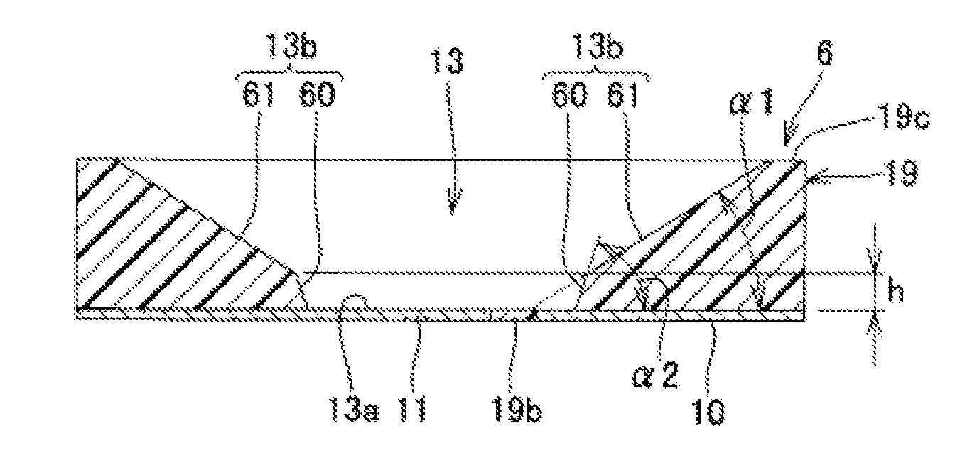
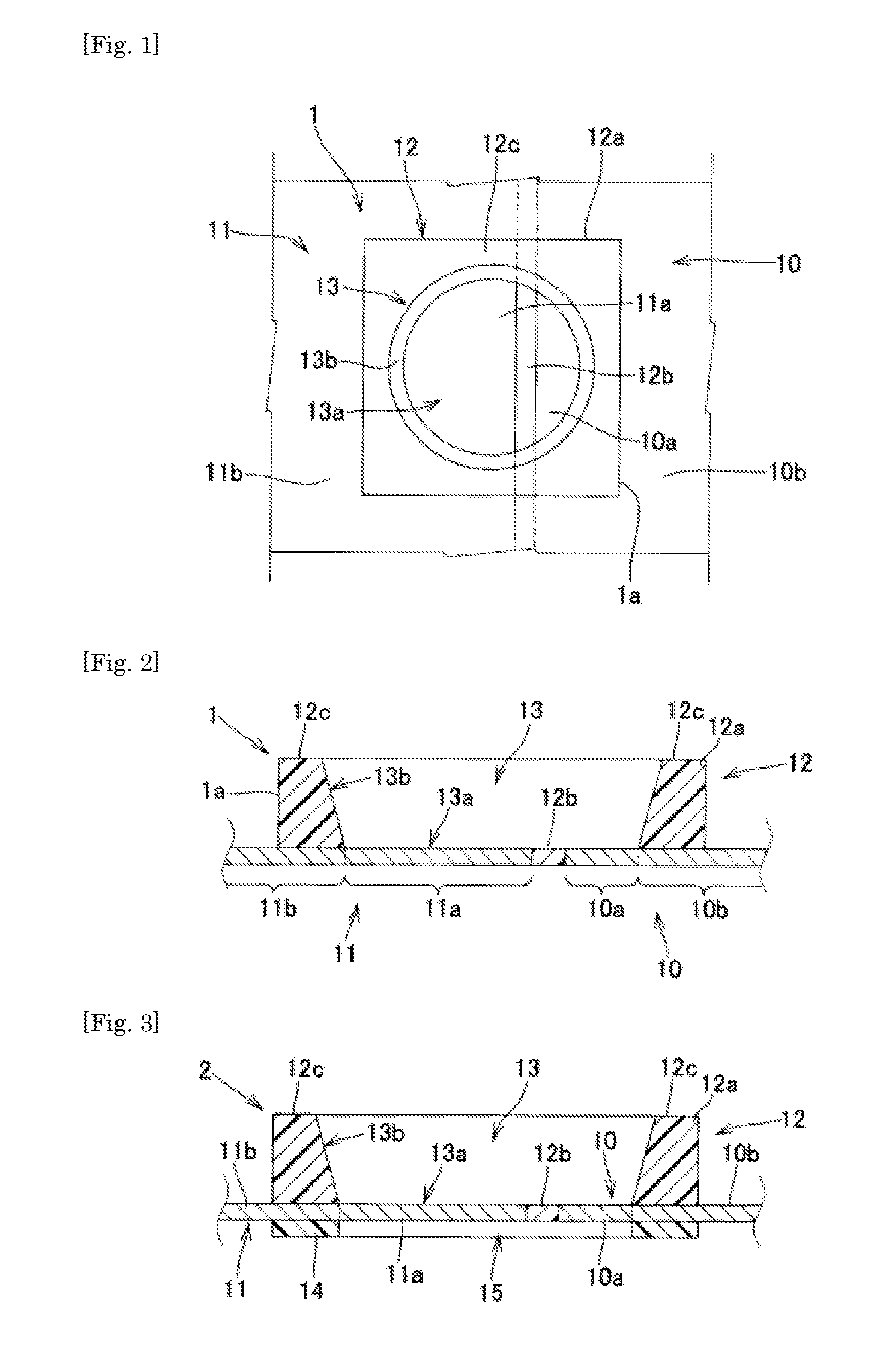
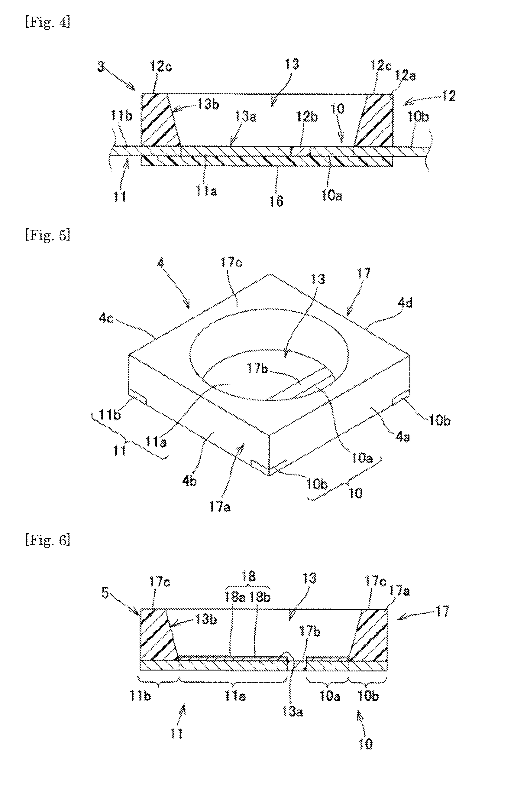
The present invention provides a molded resin body for a surface-mounted light-emitting device with good optical reflectance and mass production efficiency. The molded resin body has a concave portion with a specific roughness range and a smooth opening surface, resulting in reduced deformation and breakage during mold release. The use of a cured resin body having a predetermined glass transition temperature, optical reflectance, and retention rate ensures long-term light emission. The molded resin body design also prevents chemical degradation and resin chipping, improves product yield, and simplifies manufacturing.

Problems solved by technology

However, Ag has a problem in that Ag reacts with halogen ion and sulfur contained in the atmosphere or sealing resin to generate substances which discolor the reflective film surface into dark brown, such as halides, e.g., chlorides (AgCl) and sulfides (Ag2S), with the progress of the operation time of the surface-mounted light-emitting device, so that the optical reflectance is reduced.
Also due to the characteristic, Ag has a problem of reducing the optical reflectance.
However, since the Ag—Au alloy plating layer contains an alloy containing Au in which the Ag content is limited to less than 50 mass % as the main component, the formation operation thereof is complicated.
Further, since the thickness is 0.1 μm or more and 0.6 μm or less, the cost also becomes high.
However, in the mold release process of (d), the mold releasability of the molded resin body from the mold is very poor, and therefore there is a problem in that the deformation of the molded resin body is likely to occur and, depending on circumstances, the cohesive failure occurs, so that the molded resin body is broken.
Therefore, in the former manufacturing method, the defective product ratio sometimes becomes very high.
Furthermore, in the above-described former manufacturing method, there is a problem in that chipping occurs in the molded resin body in a portion where the molded resin body having the concave portion and the lead frame contact each other and a resin burr is formed at the bottom portion of the concave portion of the molded resin body, so that the product yield decreases.

Method used


Image

  • Molded resin body for surface-mounted light-emitting device, manufacturing method thereof, and surface-mounted light-emitting device
  • Molded resin body for surface-mounted light-emitting device, manufacturing method thereof, and surface-mounted light-emitting device
  • Molded resin body for surface-mounted light-emitting device, manufacturing method thereof, and surface-mounted light-emitting device

Examples


synthesis example 1

[0405]A stirrer, a dropping funnel, and a condenser tube were set in a four-necked 5-L flask. To this flask were added 1,800 g of toluene and 1,440 g of 1,3,5,7-tetramethylcyclotetrasiloxane, and then the flask was heated and stirred in a 120° C. oil bath. A mixed liquid of 200 g of triallyl isocyanurate, 200 g of toluene, and 1.44 mL of a xylene solution of platinum-vinylsiloxane complex (platinum content: 3% by weight) was added dropwise over 50 minutes. The obtained solution was heated and stirred as it was for 6 hours, and then unreacted 1,3,5,7-tetramethylcyclotetrasiloxane and toluene were distilled off under reduced pressure. It was found by the 1H-NMR measurement that the obtained compound had the structure obtained by a reaction of a part of the SiH groups of 1,3,5,7-tetramethylcyclotetrasiloxane with trially isocyanurate shown in the following [Chemical Formula 33].

synthesis example 2

[0406]A 2 L autoclave was charged with 720 g of toluene and 240 g of 1,3,5,7-tetramethylcyclotetrasiloxane. Then, the gas phase was replaced by nitrogen, and then heated and stirred at a jacket temperature of 50° C. A mixed liquid of 171 g of allyl glycidyl ether, 171 g of toluene, and 0.049 g of a xylene solution of platinum-vinylsiloxane complex (platinum content: 3% by weight) was added dropwise over 90 minutes. After the completion of the dropwise addition, the jacket temperature was raised to 60° C., and then a reaction was allowed to proceed for 40 minutes. It was confirmed that the reaction rate of allyl groups was 95% or more by the 1H-NMR.

[0407]A mixed liquid of 17 g of triallyl isocyanurate and 17 g of toluene was added dropwise to the obtained reaction mixture. Then, the jacket temperature was raised to 105° C., and then a mixed liquid of 66 g of triallyl isocyanurate, 66 g of toluene, and 0.033 g of a xylene solution of platinum-vinylsiloxane complex (platinum content: 3...

formulation example 1

[0409]Components were mixed in the proportions shown in Table 1 to prepare thermosetting resin compositions A to D.

TABLE 1ComponentsThermosetting resin compositionTypeCompound nameABCD(A)Triallylisocyanurate40.2 g 2.9 g19.4 g58.3 gDiallyl monoglycidyl isocyanurate28.1 g13.9 g41.71 g (B)Product of Synthesis Example 159.8 g29.3 g88.21 g Product of Synthesis Example 260.0 g37.4 g112.48 g (C)Xylene solution of platinum-0.05 g0.018 g 0.029 g 0.09 gvinylsiloxane complexCuring1-ethynyl-1-cyclohexanol 0.3 g 0.1 g 0.2 g0.49 gretardant


PUM

PropertyMeasurementUnit
roughnessaaaaaaaaaa
roughnessaaaaaaaaaa
size lengthaaaaaaaaaa

Abstract

A molded resin body for surface-mounted light-emitting device has cured resin body integrally molded with a plurality of leads and a concave portion to which the plurality of leads are exposed at the bottom portion, in which the ten-point average roughness (Rz) of the opening surface of the concave portion is 1 μm to 10 μm, the glass transition temperature of the cured resin body is 10° C. or higher and the glass transition temperature is a value measured using a thermomechanical analyzer (TMS) under the conditions of a temperature range of −50 to 250° C., a temperature elevation rate of 5° C. / min, and a sample size length of 1 to 5 mm, and the optical reflectance at 460 nm of the opening surface of the concave portion is 80% or more and the optical reflectance retention rate on the opening surface after heating the molded resin body at 180° C. for 72 hours is 90% or more.

Description

TECHNICAL FIELD[0001]The present invention relates to a molded resin body for surface-mounted light-emitting device, a manufacturing method thereof, and a surface-mounted light-emitting device.BACKGROUND ART[0002]A surface-mounted light-emitting device on which light-emitting elements, such as a light-emitting diode (LED) and a laser diode (LD), are mounted has a large number of advantages in that color reproduction of light with high-intensity light excellent in visibility can be achieved, the size thereof can be reduced, the power consumption is low, and long-life is achieved. Therefore, the surface-mounted light-emitting device is used as lighting devices, such as electric bulbs, downlights, base lights, streetlights, and signals, back light sources of liquid crystal displays and the like, and the like, for example, and the use thereof has rapidly expanded.[0003]A typical surface-mounted light-emitting device has a lead frame in which a pair of leads are disposed in such a manner...

Claims


Application Information

Patent Timeline
Patent Type & Authority Applications(United States)
IPC IPC(8): H01L33/62H01L33/54H01L33/60H05K13/00
CPCH01L33/62H05K13/00H01L2933/0066H01L33/60H01L2933/0033H01L33/54B29C45/14655B29C45/372H01L2224/48091H01L2224/48247H01L2224/45144C08G77/12C08G77/20C08L83/04H01L2924/01322H01L24/97H01L2924/12041C08G77/54C08G77/14H01L2924/15747H01L2924/181H01L2924/12042H01L2924/12044H01L2924/12036H01L2224/48257C08K5/34924Y10T428/24802Y10T428/24851Y10T428/24917H01L2924/00014H01L2924/00C08L83/00C08L83/14
Inventor TOZAWA, TOMOKAZUIWAHARA, TAKAHISAOGOSHI, HIROSHIHIRABAYASHI, KAZUHIKOOZAKI, SHUHEIIBA, SATOAKIKANAI, KAZUAKIKAKEHASHI, YASUSHIMANABE, TAKAOHORI, MITSUHIRONARITA, RYOICHI
Owner KANEKA CORP
Learn More