Method for operating a separately excited electric machine in a motor vehicle

a technology of electric machines and motor vehicles, which is applied in the direction of electric generator control, generator control by field variation, dynamo-electric converter control, etc., can solve the problems of inability to use continuously at a higher current, unwanted voltage dips in the vehicle electrical system, and shorten the time for reaching the nominal current intensity. , the effect of preventing the flow of excess current through the rotor winding

Active Publication Date: 2015-02-19
ROBERT BOSCH GMBH +1
View PDF12 Cites 6 Cited by
  • Summary
  • Abstract
  • Description
  • Claims
  • Application Information

AI Technical Summary

Benefits of technology

[0019]According to another specific embodiment of the present invention, for a brief period of time immediately after the beginning of the flow of current, the rotor winding is driven by a voltage signal having a pulse duty factor (referred to as the “third pulse duty factor” in the scope of this application), which, in continuous operation, would produce a current value that is greater than the nominal current intensity. In this manner, the period of time for reaching the nominal current intensity may be further shortened, as is apparent, e.g., from FIG. 3B. In this context, the rotor winding does not have to be configured for continuous operation at the third pulse duty factor. Thermal destruction of the rotor winding may be prevented by selecting the corresponding driving time interval to be sufficiently short. As mentioned, certain delays in reaching the specific current values in a rotor winding always occur, due to the coil inductance. Thus, the flow of current through the rotor winding only builds up over a certain, ascertainable period of time (in the present invention, e.g., roughly 50 ms). Therefore, the flow of excess current through the rotor winding may be prevented by reducing the pulse duty factor again after a short peri...

Problems solved by technology

However, when the electrical system voltage (which is provided, in the meantime, e.g., by the battery) drops, this causes the switching-on of the generator to take up a relatively long time span, since the exciting curr...

Method used


Image

  • Method for operating a separately excited electric machine in a motor vehicle
  • Method for operating a separately excited electric machine in a motor vehicle
  • Method for operating a separately excited electric machine in a motor vehicle

Examples


Embodiment Construction

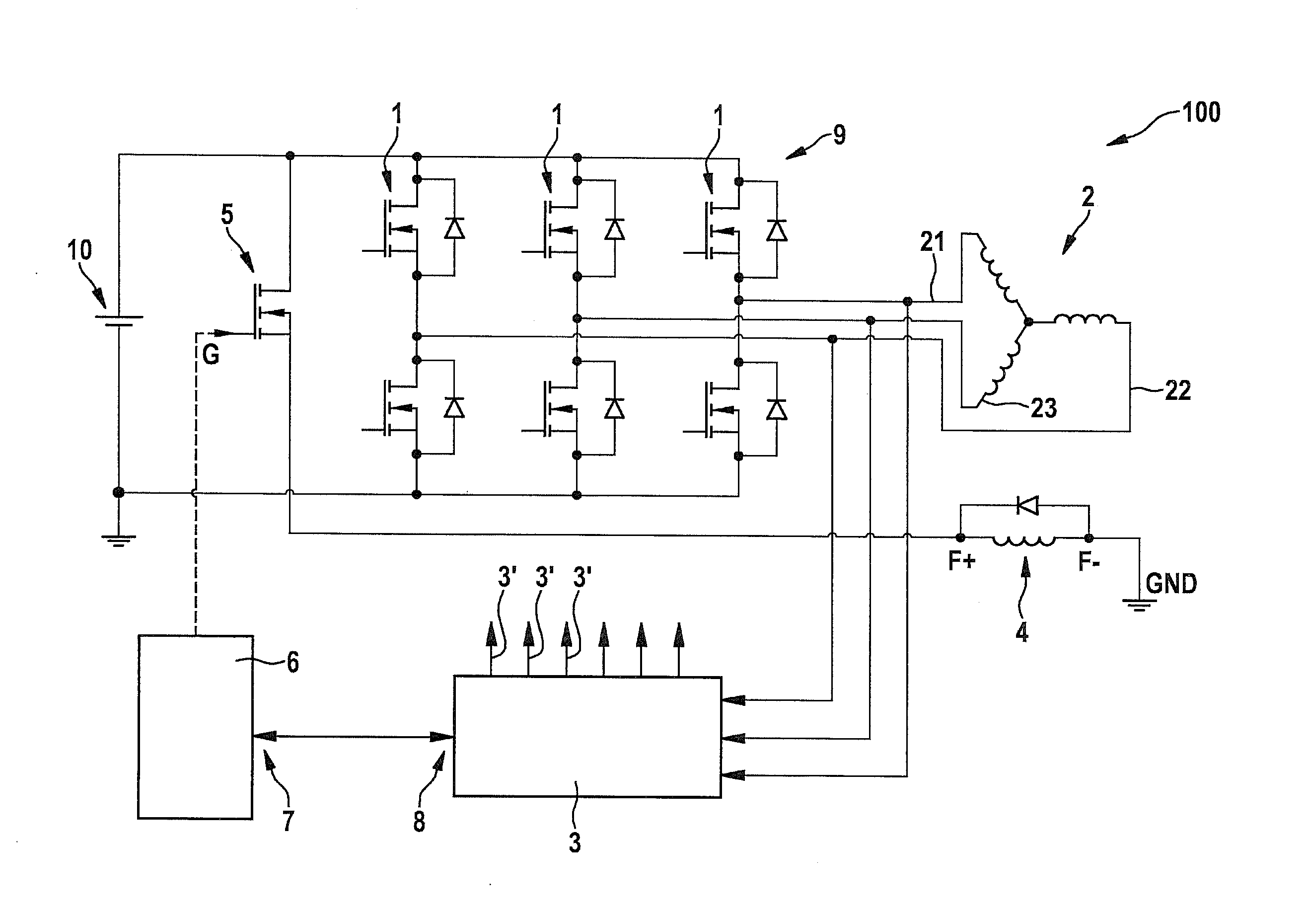
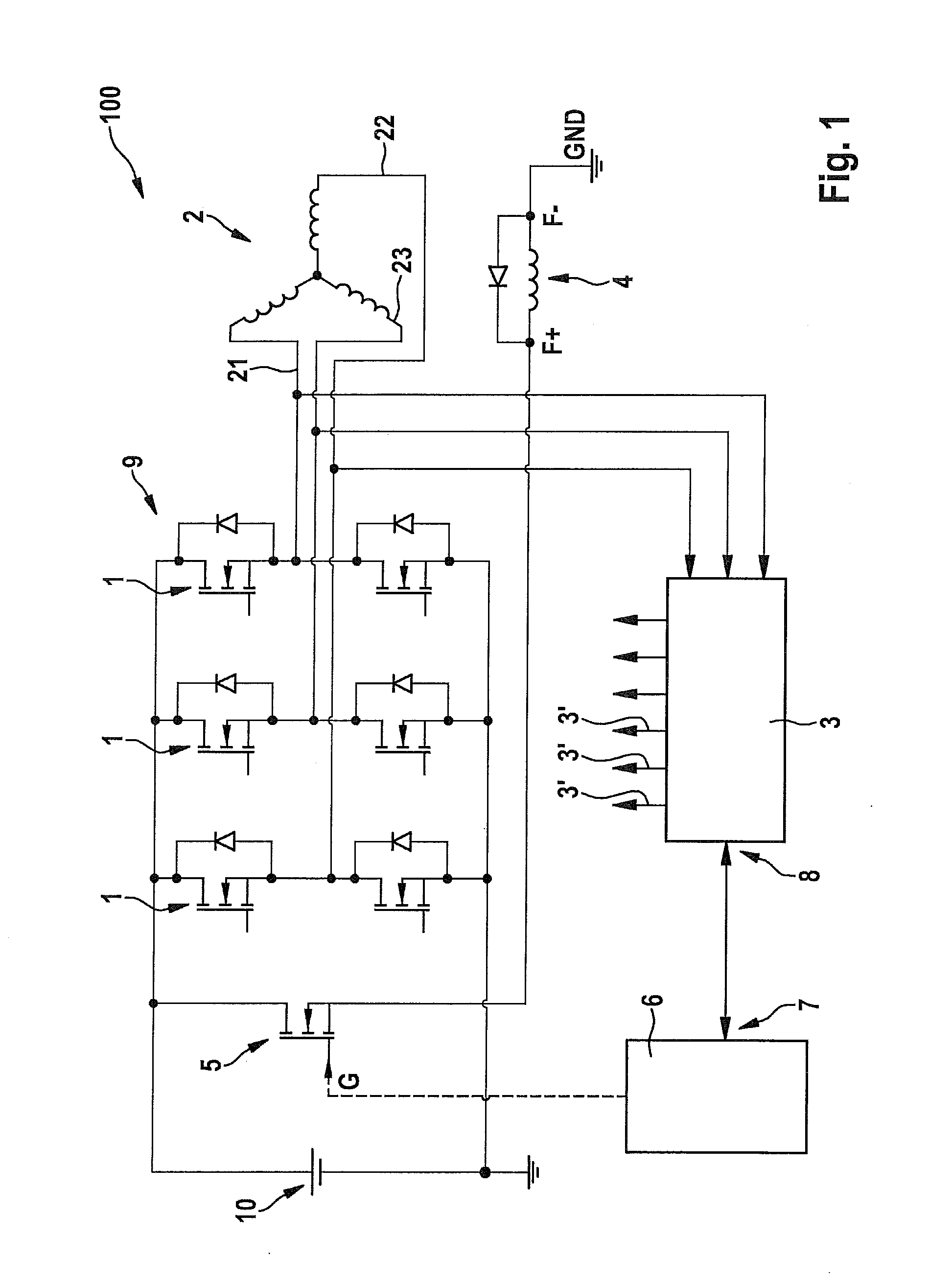
[0032]FIG. 1 shows a circuit diagram of a starter generator of a motor vehicle operable in accordance with a specific embodiment of the present invention. The starter generator is denoted, on the whole, by reference numeral 100 and includes a stator 2 having three phases 21, 22, 23.

[0033]A rotor winding 4 is provided, to which a pulse-width modulated voltage signal of a voltage source 10, e.g., a battery, may be applied, using timing device 5, e.g., a suitable metal oxide semiconductor field effect transistor (MOSFET). To this end, timing device 5 is controlled, e.g., at a gate terminal G, by a control unit 6, using a control signal.

[0034]Control unit 6 may be connected to a rectifier control unit 3 via interfaces 7, 8; the rectifier control unit triggering active circuit elements 1 of a rectifier 9 via outputs 3′; the rectifier being connected to phases 21, 22, 23 of stator 2, e.g., in accordance with a rotor position. Active circuit elements 1 of rectifier 9 may also be correspond...


PUM


Abstract

A method for operating a separately excited electric machine, in particular, a generator of a motor vehicle, where an exciting current flows through a rotor winding of the electric machine at a nominal current intensity during a normal operation and at a holding current intensity in an idling operation; the holding current intensity being greater than zero and less than the nominal current intensity.

Description

FIELD OF THE INVENTION[0001]The present invention relates to a method for operating a separately excited electric machine in a motor vehicle, as well as to a processing unit for implementing it.BACKGROUND INFORMATION[0002]Electric machines for use in motor vehicles, in the form of the starting motor (motor) and the alternator (generator), are well-known. In modern vehicles, alternating current generators, which have a claw-pole configuration and are (separately) excited electrically, may be used as generators. As a rule, rectifiers based on semiconductor diodes may be used for rectifying the alternating current generated.[0003]However, due to the increasing need for electrical energy in the vehicle, the effort to reduce fuel consumption and lower emissions, as well as the desire to be able to combine the advantages of an electric motor with those of an internal combustion engine, electric machines having a dual function, so-called starter generators, are also being used increasingly...

Claims


Application Information

Patent Timeline
IPC IPC(8): H02P9/48
CPCH02P9/48H02P9/08H02J7/1446H02P9/30Y02T10/92
Inventor DEAK, ISTVAN
Owner ROBERT BOSCH GMBH
Why Eureka
Try Eureka