
Background correction in emission spectra

a background correction and emission spectra technology, applied in the field of optical emission spectroscopy, can solve the problems of time-consuming technique, simple and relatively unreliable technique, and difficult to accurately assess the concentration of elements

Active Publication Date: 2015-03-05
THERMO ELECTRON MFG
View PDF3 Cites 23 Cited by
  • Summary
  • Abstract
  • Description
  • Claims
  • Application Information

AI Technical Summary

Benefits of technology

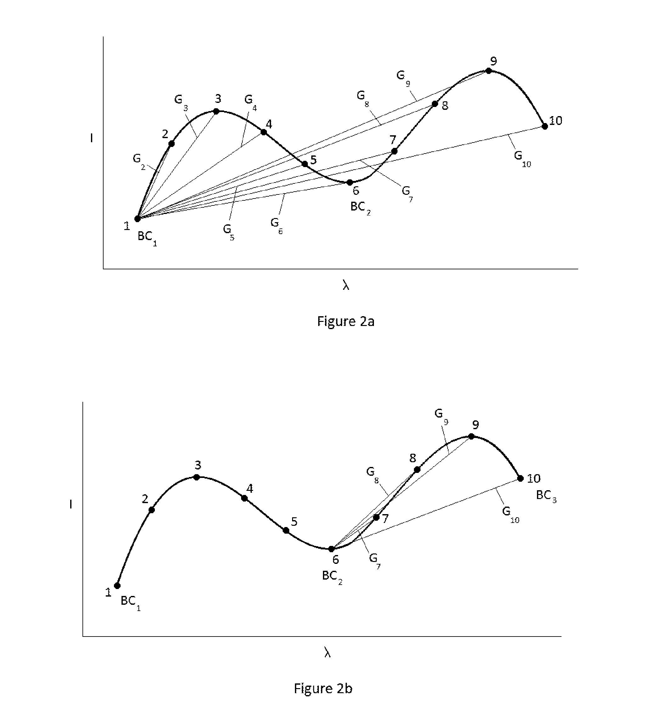
The patent text describes a method for improving the accuracy of data obtained from an emission spectrum. The method involves using a roll-up feature at the first and last data points in a portion of the spectrum to identify at least one intermediate background correction point. This helps to account for any slight dip in the intensity of the spectral lines of interest and ensures more accurate background correction. The technical effect of this method is to provide a more accurate understanding of the data obtained from an emission spectrum.

Problems solved by technology

A problem which exists in this and other analytical techniques involving emission spectra is that a continuum background can distort the shape of the spectral lines making an accurate assessment of element concentration difficult.
The simplest and a relatively unreliable technique is for the user to guess the wavelength value of one or two background points and use these wavelength values to apply a background correction in the determination of a concentration estimate.
However this technique is time consuming and requires a relatively skilled technician to select suitable background points.
Similar problems exist in infra-red, gas chromatography, liquid chromatography and ultraviolet analytical instruments where changes in conditions affect the measurements made by the instrument.

Method used


Image

  • Background correction in emission spectra
  • Background correction in emission spectra
  • Background correction in emission spectra

Examples


Embodiment Construction

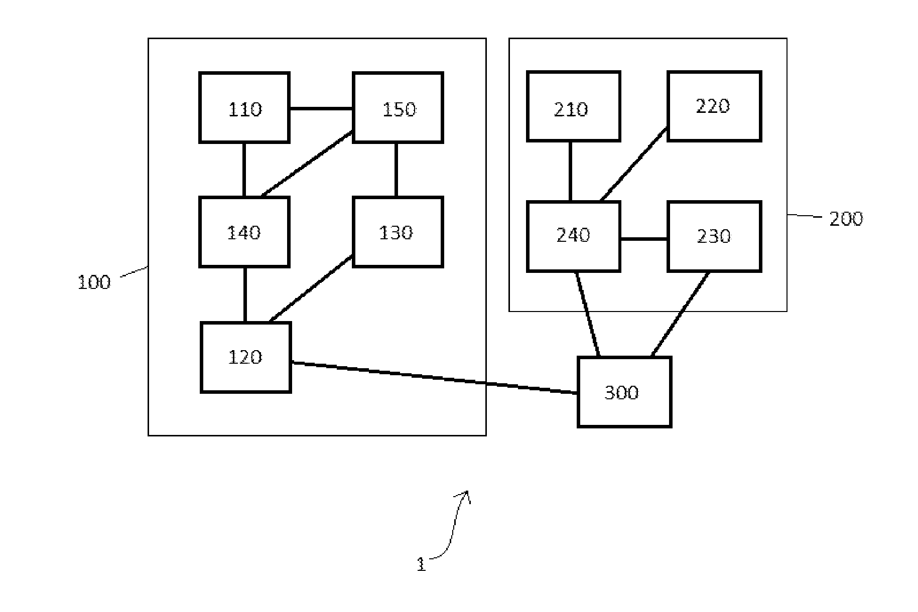
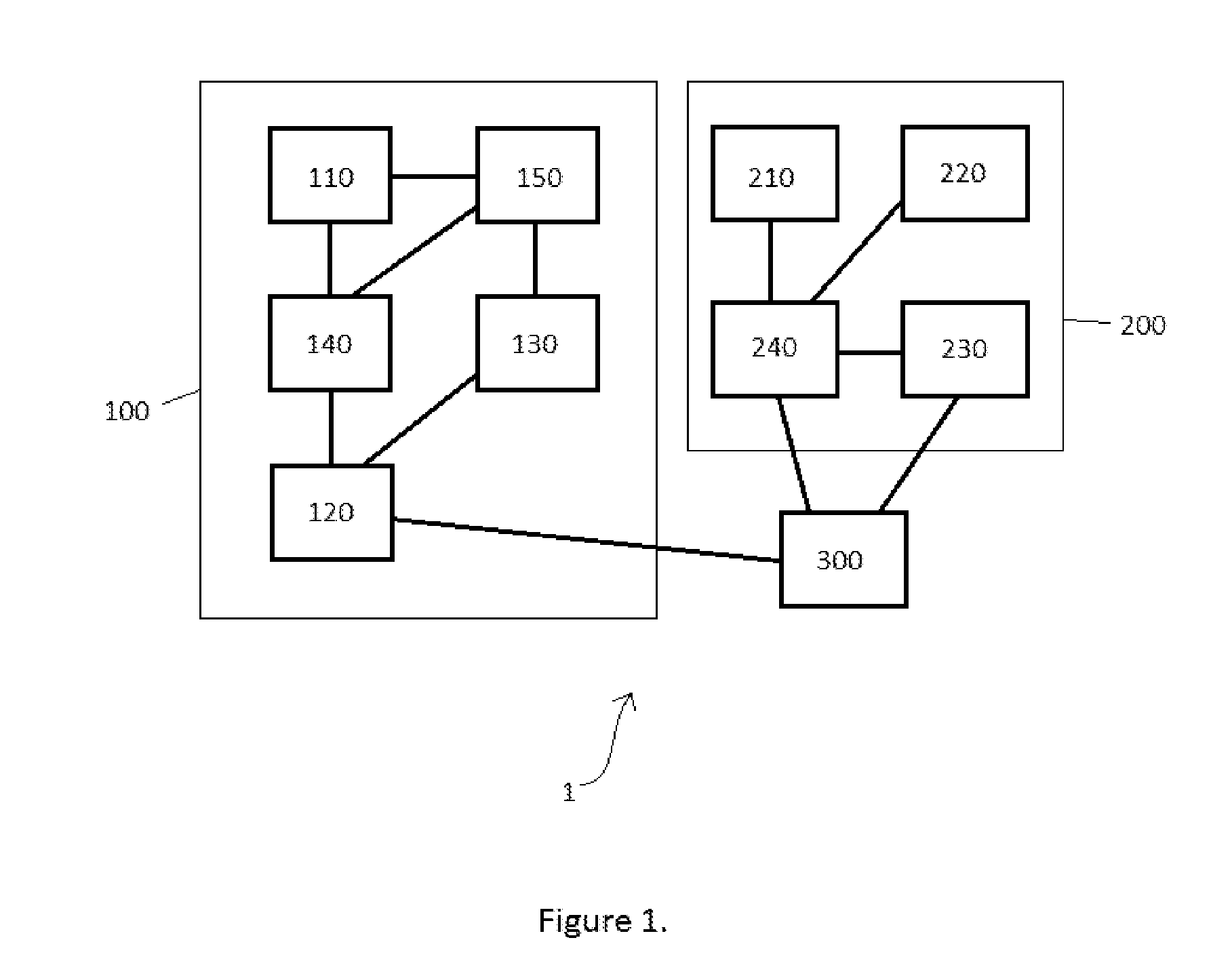
[0050]FIG. 1 is a schematic depiction of a system 1 of the present invention. System 1 comprises an optical emission source 100, and a spectrometer 200. Optical emission source 100 may be any form of optical emission source, including but not limited to inductively coupled plasma and microwave induced plasma sources. In this example optical emission source 100 comprises an inductively coupled plasma optical emission source. Inductively coupled plasma optical emission source 100 further comprises a sample introduction system 110, a source control system 120, a RF generator 130, a gas control system 140, and a torch 150. Sample introduction system 110 comprises liquid sample uptake apparatus, a nebuliser and a spray chamber for creating a stream of droplets of sample and delivering the stream into torch 50, utilizing gas controlled by gas control system 140. Torch 150 is a conventional inductively coupled plasma torch as is known in the art. Torch 150 has an exit end placed within a m...


PUM


Abstract

A method for deriving a background-corrected portion of a measured optical emission spectrum comprising the steps of identifying two or more background correction points from the portion of the measured emission spectrum; deriving a background correction function fitted to the identified background correction points, and applying the background correction function to the portion of the measured emission spectrum so as to produce a background-corrected portion of the emission spectrum, wherein the background correction points are identified from the measured data points by consideration of the gradients between the measured data points.

Description

FIELD OF THE INVENTION[0001]This invention relates to the field of optical emission spectroscopy, and in particular to spectral data processing to provide background-corrected portions of spectral emission data. It may be applied, for example, in inductively coupled plasma or microwave optical emission spectrometry.BACKGROUND OF THE INVENTION[0002]Inductively coupled plasma and microwave induced plasma optical emission spectroscopy (ICP-OES and MIP-OES respectively) are analytical techniques for determining the concentration of elements in a sample. A sample solution is injected into a plasma source, the temperature of which vaporises the sample, destroys any chemical bonds, ionises atoms and causes electronic excitation of the atoms and ions. A plasma spectrum consists of a continuum background and discrete spectral lines at wavelengths characteristic of any element contained in the sample. The intensity of any given spectral line is proportional to the concentration of the element...

Claims


Application Information

Patent Timeline
Patent Type & Authority Applications(United States)
IPC IPC(8): G01J3/02G01J3/443
CPCG01J3/443G01J3/0297G01J3/28G01N21/73
Inventor HARTWELL, STEPHENBAILEY, NIGEL COOPER
Owner THERMO ELECTRON MFG
Learn More