Sic matrix fuel cladding tube with spark plasma sintered end plugs

a fuel cladding tube and spark plasma technology, applied in the direction of nuclear engineering, greenhouse gas reduction, nuclear elements, etc., can solve the problems of pushed reactor operating temperature and cladding radiation exposure to extreme limits, and none of them proved successful in a nuclear environmen

Active Publication Date: 2015-03-19
WESTINGHOUSE ELECTRIC CORP +1
View PDF3 Cites 40 Cited by
  • Summary
  • Abstract
  • Description
  • Claims
  • Application Information

AI Technical Summary

Benefits of technology

[0032]The operating parameters of the generally known spark plasma process (SPS process), except for particular critical ranges disclosed and discovered herein, are preferably: applying temperature rises at the plug/cladding gaps/interface of up to 1,500° C./min., at a rapid rate of preferably 100° C./min. to 1,000° C./min., most preferable 1,000° C./min. and up to a peak temperature of 2,500° C., preferably 1,800° C. to 2,150° C., most preferably 2,100° C. at 1.0 to 6.0 minutes and 5.0 to 10 MPa. As shown in FIG. 2 vs. FI

Problems solved by technology

There are problems associated with metal clad fuel rods.
They can wear if contacted by debris that may be present in the cooling water mentioned before.
In addition, continuing utility industry demands have pushed reactor operating temperatures and cladding radiation exposure to extreme limits.
Several sealing technologies have been explored in the recent past; but to date none of them proved successful in a nuclear environment, which is essential here.
The above ceramic models are no longer experiments and are generally shown to have high mechanical strength, and are thought capable of realizing the required gas-tightness for a nuclear reactor; however, these joining technologies failed to show th

Method used


Image

  • Sic matrix fuel cladding tube with spark plasma sintered end plugs
  • Sic matrix fuel cladding tube with spark plasma sintered end plugs
  • Sic matrix fuel cladding tube with spark plasma sintered end plugs

Examples


example

[0060]A “Ceramic Composite” consisting of a 12 foot (365.76 cm) long extruded stoichiometric alpha phase nuclear reactor SiC tube, for containing nuclear fuel in a reactor, with an inner diameter of 0.32 inches (0.8128 cm) and a wall thickness of 0.015 inches (0.0381 cm) at a density of 95% of the SiC theoretical density, is wound with a 0.026 inch (0.066 cm) layer of SiC composite consisting of 6 layers of windings of stoichiometric beta phase SiC fibers and is infiltrated with beta phase stoichiometric SiC using chemical vapor infiltration to a net density for the composite of greater than 80% of the SiC theoretical density.

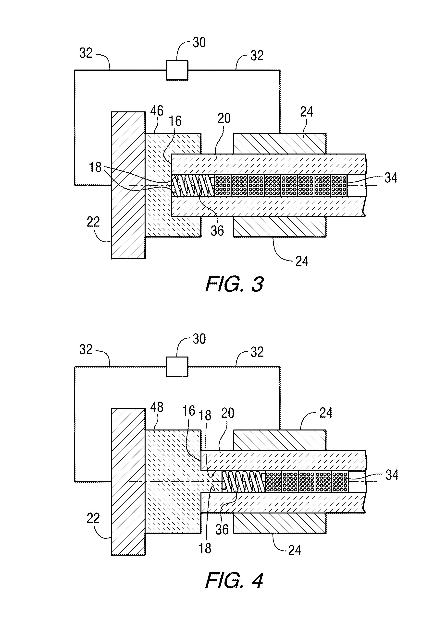
[0061]This “Ceramic Composite” was sealed with extruded stoichiometric alpha phase end plugs with highly polished inner and upper tube seal faces as in FIG. 4, applied using plasma spark sintering as well known and previously defined in a chamber filled with helium at 375 psi at ambient condition. The heating rate was 200° C. / minute, with a bonding pressure of ...


PUM

PropertyMeasurementUnit
Temperatureaaaaaaaaaa

Abstract

A method of providing an end-capped tubular ceramic composite for containing nuclear fuel (34) in a nuclear reactor involves the steps of providing a tubular ceramic composite (40), providing at least one end plug (14, 46, 48), applying (42) the at least one end plug material to the ends of the tubular ceramic composite, applying electrodes to the end plug and tubular ceramic composite and applying current in a plasma sintering means (10, 50) to provide a hermetically sealed tube (52). The invention also provides a sealed tube made by this method.

Description

BACKGROUND[0001]1. Field[0002]The invention relates to a fuel rod cladding tube made out of silicon carbide (herein referred as SiC), regardless the cladding design architecture (monolithic, duplex with monolithic SiC on the inside and a composite made with SiC fibers and SiC matrix on the outside, etc.) with a spark plasma sinter sealed end plug.[0003]2. Description of Related Art[0004]In a typical nuclear reactor, such as a pressurized water (PWR), heavy water (such as a CANDU) or a boiling water reactor (BWR), the reactor core includes a large number of fuel assemblies, each of which is composed of a plurality of elongated fuel elements or fuel rods. The fuel rods each contain nuclear fuel fissile material such as at least one of uranium dioxide (UO2), plutonium dioxide (PuO2), uranium nitride (UN) and / or uranium silicide (U3Si2); with possible additions of, for example, boron or boron compounds, gadolinium or gadolinium compounds and the like either on or in pellets, usually in ...

Claims


Application Information

Patent Timeline
IPC IPC(8): G21C3/10C04B37/02C04B37/00
CPCG21C3/10C04B37/02C04B37/001C04B37/005C04B37/021C04B2235/6562C04B2235/6567C04B2235/666C04B2237/36C04B2237/365C04B2237/38C04B2237/40C04B2237/52C04B2237/765C04B2237/80G21C3/07G21C21/02C04B2237/704C04B2237/84C04B2235/77C04B2235/5244Y02E30/30
Inventor XU, PENGLAHODA, EDWARD J.HALLSTADIUS, LARSCHOI, JOON HYUNGHIGUCHI, SHINICHIKANO, FUMISHA
Owner WESTINGHOUSE ELECTRIC CORP
Why Eureka
Try Eureka