Apparatus for production of polymeric nanofibers

Active Publication Date: 2015-04-23
CUMMINS FILTRATION INC
View PDF7 Cites 7 Cited by
  • Summary
  • Abstract
  • Description
  • Claims
  • Application Information

AI Technical Summary

Benefits of technology

[0007]The present invention is directed toward a spinning apparatus for making polymeric nanofibers, comprising: (a) a high speed rotating member comprising a spinning disk or a spinning bowl wherein the rotating member has an edge and, optionally, the rotating member can be heated by induction heating; (b) a protecting shield affixed to the edge of the rotating member to form enclosed serrations wherein the protecting shield is positioned on the top of the spinning disk or the bottom of the spinning bowl; (c) a stationary shield on the bottom of the rotating member; and (d) an optional stretching zone.
[0008]This invention is further directed toward polymeric nanofibers produced from this spinning app

Problems solved by technology

Polymer nanofibers can be produced from solution-based electrospinning or electroblowing, however, they have very high processing cost, limited throughputs and low productivity.
Melt blowing nanofiber processes that randomly lay down fibers do not provide adequate uniformity at sufficiently high throughputs for most end use applications.
A problem with melt-blown nanofibers or small microfibers, exposed on the top of the web, they are very fragile and easily crushed by normal handling or contact with some object.
Also, the multilayer nature of such webs increases their thickness and weight, and also introduces some complexity in manufacture.
Otherwise, there would not be uniform and smooth thin film flow on the inner surface of the spinning disk.
If the disk temperature is too h

Method used


Image

  • Apparatus for production of polymeric nanofibers
  • Apparatus for production of polymeric nanofibers
  • Apparatus for production of polymeric nanofibers

Examples


example 1

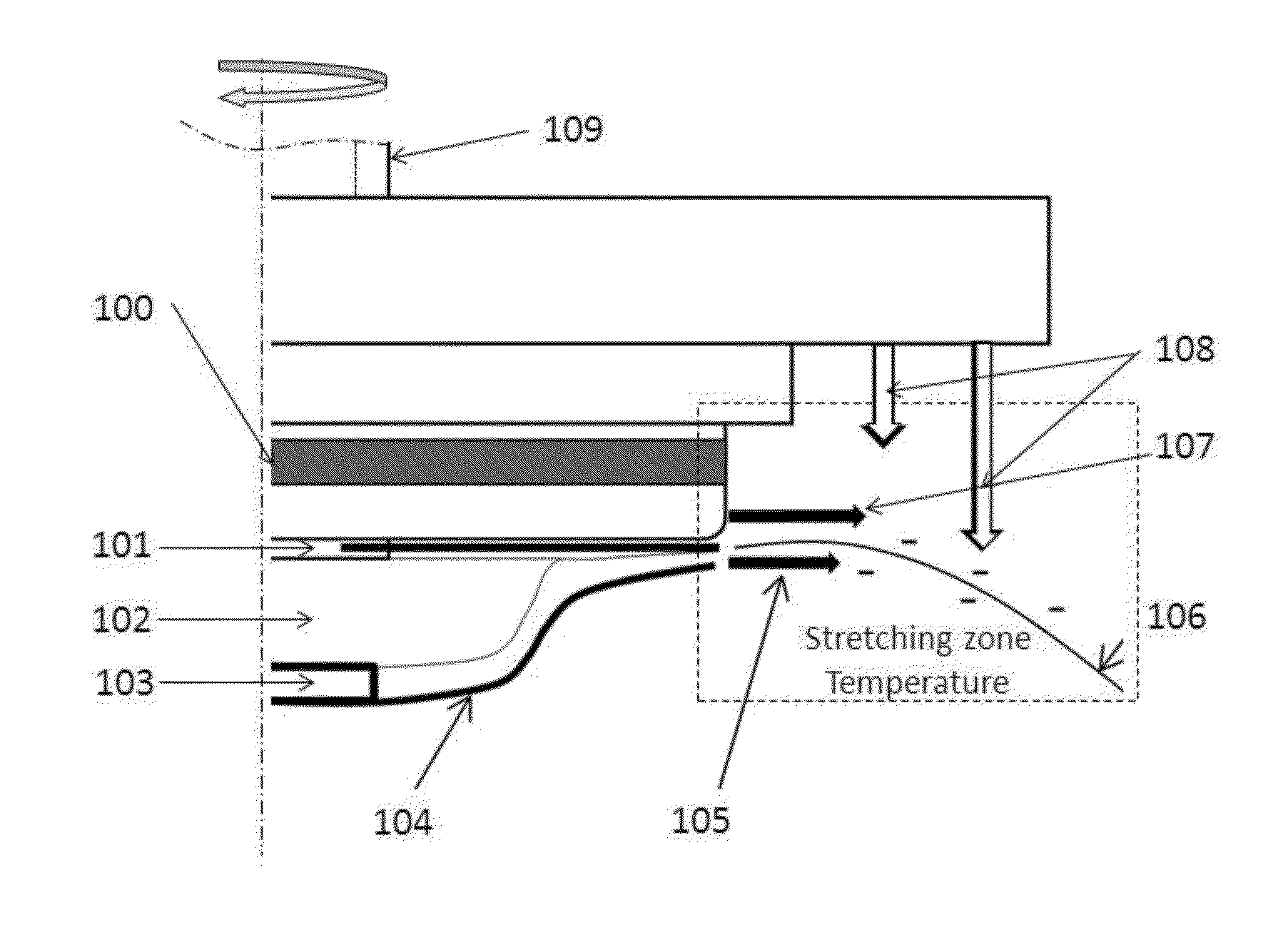
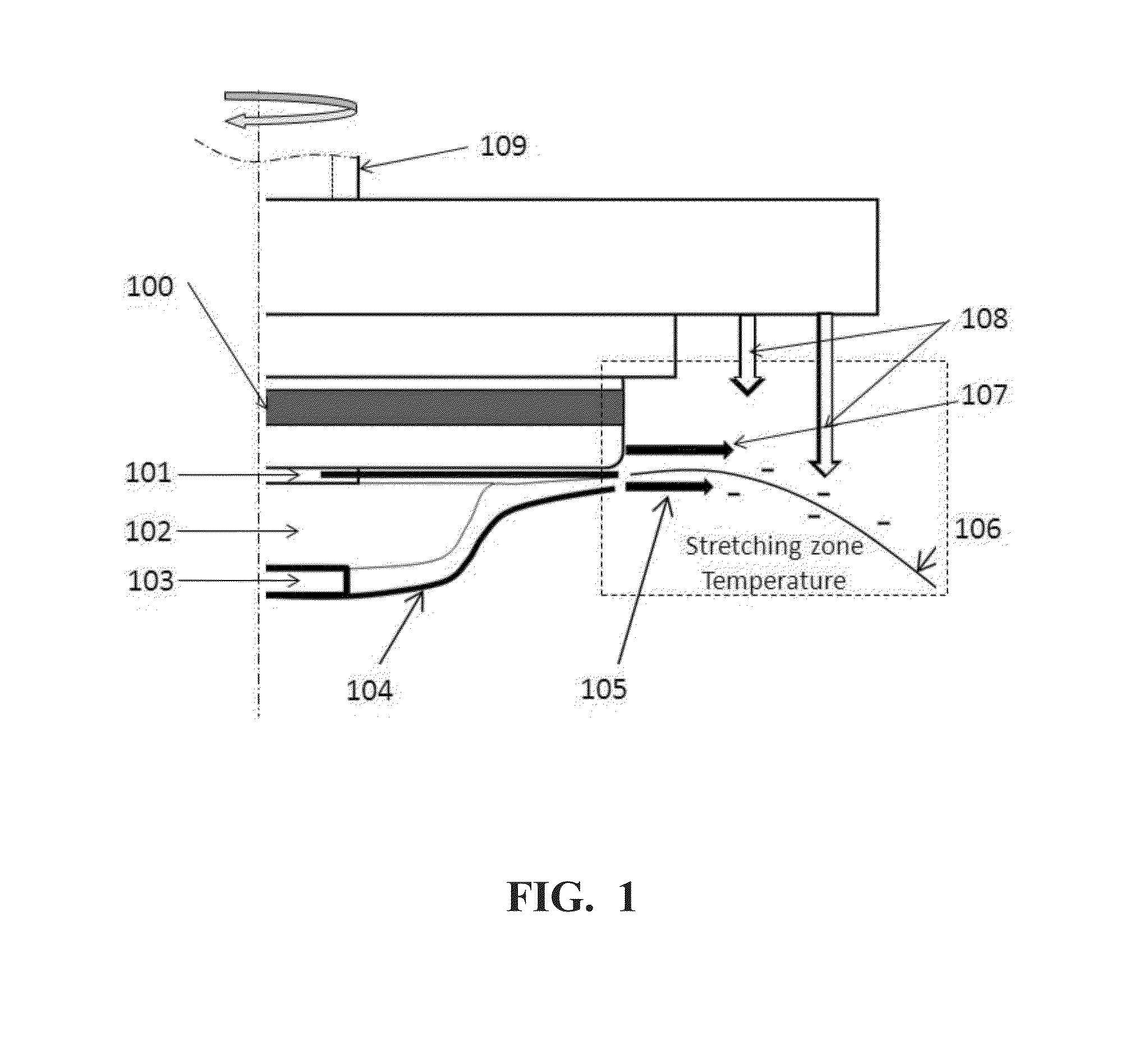
[0092]Continuous fibers were made by a spin disk with the enclosed serrations and the stationary shield using an apparatus as illustrated in FIG. 1, from a polypropylene (PP) homopolymer, Metocene MF650Y from LyondellBasell. It has Mw=75,381 g / mol, melt flow rate=1800 g / 10 min (230° C. / 2.16 kg), and zero shear viscosity of 9.07 Pa·S at 200° C. A PRISM extruder with a gear pump was used to deliver the polymer melt to the rotating spin bowl through melt transfer line. The temperature of the spinning melt from the melt transfer line was set to 240° C. The temperature of spin disk edge was about 200° C. The stretching zone heating air was set at 200° C. The stretching zone air through the gap between the disk and the stationary shield was set at 200° C. with the air flow rate of 50 SCFH. The downward shaping air was set at 150° C. The shaping air flow was set at 50 SCFH. The rotation speed of the spin disk was set to a constant 12,000 rpm.

[0093]The fiber size was measured from an image ...


PUM

PropertyMeasurementUnit
Fractionaaaaaaaaaa
Fractionaaaaaaaaaa
Diameteraaaaaaaaaa

Abstract

The present invention is directed toward an apparatus comprising a high speed rotating disk or bowl for nanofiber spinning from the rotational sheared thin film fibrillation at the enclosed serrations with the optimized stretching zone to produce the defects-free nanofibrous web and nanofibrous membrane comprising a nanofiber network with a number average nanofiber diameter less than 500 nm that yield the crystallinity higher than the polymer resin used in making the web.

Description

FIELD OF THE INVENTION[0001]This invention relates to an improved centrifugal nanofiber spinning apparatus for producing the defects-free nanofibrous web and nanofibrous membrane comprising a nanofiber network with a number average nanofiber diameter less than 1000 nm.BACKGROUND[0002]Polymer nanofibers can be produced from solution-based electrospinning or electroblowing, however, they have very high processing cost, limited throughputs and low productivity. Melt blowing nanofiber processes that randomly lay down fibers do not provide adequate uniformity at sufficiently high throughputs for most end use applications. The resulting nanofibers are often laid on substrate layer of coarse fiber nonwoven or microfiber nonwoven to construct multiple layers. A problem with melt-blown nanofibers or small microfibers, exposed on the top of the web, they are very fragile and easily crushed by normal handling or contact with some object. Also, the multilayer nature of such webs increases their...

Claims


Application Information

Patent Timeline
IPC IPC(8): D01D4/02D01F6/00
CPCD01F6/00D01D4/025D01D5/18Y10T428/298Y10T442/60
Inventor HUANG, TAODALY, THOMAS PATRICKDILWORTH, ZACHARY R.
Owner CUMMINS FILTRATION INC
Why Eureka
Try Eureka