Lens antenna with electronic beam steering capabilities

a beam steering capability and antenna technology, applied in the field of radio engineering, can solve the problems of reducing radiation efficiency and antenna gain value, difficult to optimize the characteristics of antenna elements in those antennas, and difficulty in adjusting the alignment probability of antennas, etc., to achieve the effect of increasing radiation efficiency, increasing directivity value, and increasing gain

Inactive Publication Date: 2015-04-30
OBSHCHESTVO S OGRANICHENNOJ OTVETSTVENNOSTYU RADIO GIGABIT
View PDF11 Cites 250 Cited by
  • Summary
  • Abstract
  • Description
  • Claims
  • Application Information

AI Technical Summary

Benefits of technology

[0039]Making of antenna elements as horn antenna elements placed on the plane surface of the dielectric lens results in increase of the directivity value and provides at the same time continuous scanning angle range in contrast to the known antennas.
[0040]Furthermore, the lens antenna used for example in radio communications according to the described invention has increased radiation efficiency keeping continuous scanning angle range and, consequently, increased gain relatively to the known lens antennas with planar feed elements that also provide continuous scanning angle range.
[0041]In particular, utilization of horn antenna elements placed on the plane surface of the dielectric lens allows increasing the antenna directivity in comparison to the known integrated lens antennas by selecting geometric parameters of antenna elements (a shape and dimensions of a horn). Horn antenna elements have metallic structure with low conducting losses that additionally provides high radiation efficiency and, consequently, a high gain value in such antennas.
[0042]Utilization of integrated lens antennas according to the present invention having switched horn antenna elements placed on the plane surface of the dielectric lens, also allows to eliminate the limitation of the known reflector antennas, in particular, it helps to increase antenna aperture efficiency and, consequently, directivity by optimization of the horn parameters having continuous scanning angle range through closer arrangement of horns on the plane lens surface that is possible by using shortened wavelength for a signal propagating inside the lens body (consequently, horn dimensions are also decreased). Furthermore, positioning of the horns relatively to the lens focus is simplified in the lens antenna by placing the horns directly on the lens surface.

Problems solved by technology

However, the use of antennas with a narrow radiation pattern beam involves difficulties related to antenna alignment and probability of connection refuse in case of even small orientation changes of a radio-relay system.
However it is very difficult to perform optimization of the antenna elements characteristics in those antennas in order to provide the most efficient illumination of the collimating lens surface and, consequently, to achieve maximum directivity.
Moreover, losses in a planar structure and / or in electrical connections of integrated circuits are quite high that leads to decrease of the radiation efficiency and the antenna gain value.
However, some limitations of scanning antenna systems of similar types are also known.
They include difficulties in providing of solid angle coverage range during scanning with simultaneous maintenance of high aperture efficiency of antennas (especially with increase of beam deviation angles).
Complexity in providing of continuous scanning range in reflector antennas is caused by considerably large dimensions of horn antenna elements (in parabolic reflector antennas) or of secondary hyperbolic mirror (in Cassegrain antennas), which makes it impossible to place their phase centers close to each other and, consequently, to provide a continuous scanning angle range.
However, it leads to degradation of the antenna directivity being only 35.5 dBi due to the increased level of spillover radiation losses.
In this case, some part of the radiation from a feed horn antenna element is propagated beyond the main reflector (due to a wider radiation pattern of an antenna element), and it leads to decrease of the antenna aperture efficiency and, consequently, to decrease of its directivity.
However, as it may be clear for those skilled in the art, the increase of a number of horn antenna elements leads to antenna complexity and high cost of such antenna system.
However, those devices also increase the antenna complexity.
These limitations concern the necessity of arrangement of switched primary antenna elements on some curved surface, more often spherical surface, the necessity of precise alignment of the array of primary antenna elements in a focal plane of the main collimating device, difficulties in providing of continuous scanning angle range and high directivity of the antenna.
With further increase of the lens diameter this technique become less effective because variations of the cylindrical extension length lead to significant distortions of a plane wave front formed by the lens.
In such antenna structure it is also difficult to provide directivity maximization by variations of only planar antenna elements parameters that is needed when the lens diameter is large.
Moreover, implementation of antenna elements on a semiconductor substrate with relatively high loss level leads to small radiation efficiency that decreases the gain.
The main drawback of such configuration lies in having difficulties with optimization of primary antenna elements structure for the directivity maximization in the lens antennas with large apertures.

Method used


Image

  • Lens antenna with electronic beam steering capabilities
  • Lens antenna with electronic beam steering capabilities
  • Lens antenna with electronic beam steering capabilities

Examples


Embodiment Construction

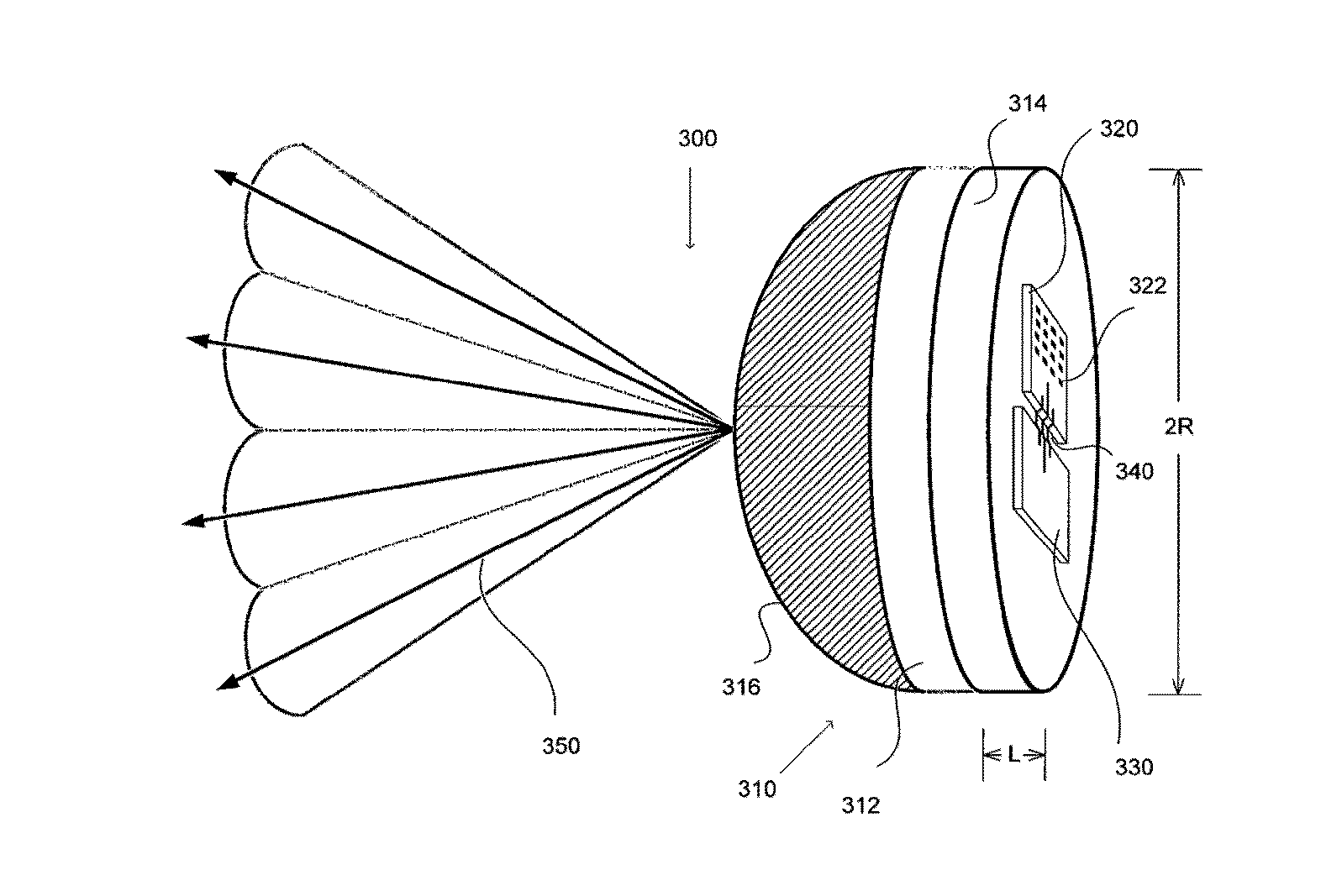
[0071]To achieve the described objects of characteristics optimization of integrated lens antennas with large dimensions (diameter is >10-20 times of wavelength in free space) it is proposed to use horn feed antenna elements in such antennas that are placed on the plane surface of the lens as it is shown in FIG. 6.

[0072]The preferred shape of the large lens providing all the required antenna characteristics for use in radio-relay communication systems is elliptical shape made of homogeneous dielectric with certain dielectric permittivity.

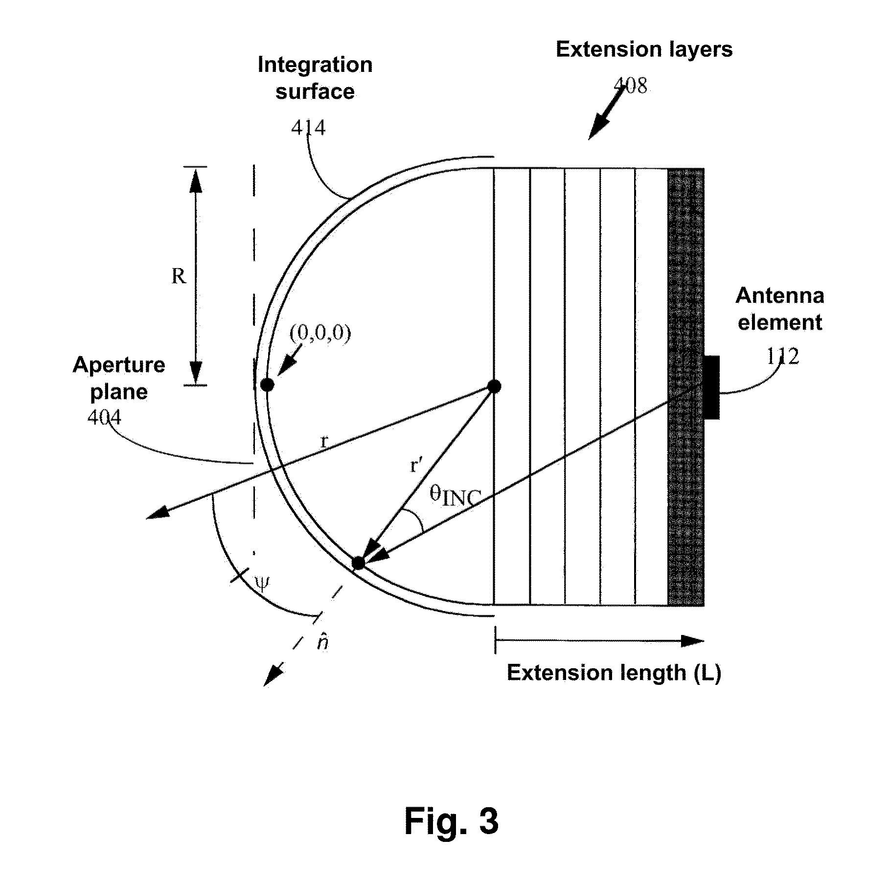
[0073]Variation of the lens geometrical parameters (either of elliptical part or the length of cylindrical extension) cannot be used for optimization of the antenna characteristics due to phase front degradations aroused on the equivalent aperture of the antenna. However, such optimization is possible by variations of the primary antenna element radiation characteristics that lead to increase in directivity of an integrated lens antenna. In particul...


PUM


Abstract

The invention discloses a lens antenna with high directivity intended for use in radio-relay communication systems, said antenna providing the capability of electronic steering of the main radiation pattern beam by switching between horn antenna elements placed on a plane focal surface of the lens. Electronic beam steering allows antenna to automatically adjust the beam direction during initial alignment of transmitting and receiving antennas and in case of small antenna orientation changes observed due to the influence of different reasons (wind, vibrations, compression and / or extension of portions of the supporting structures with the temperature changes, etc.). The technical result of the invention is the increase of the antenna directivity with simultaneously provided capability of scanning the beam in a continuous angle range and also the increase of the antenna radiation efficiency and, consequently, the increase of the lens antenna gain. This result is achieved by the implementation of horn antenna elements with optimized geometry.

Description

CROSS-REFERENCE TO RELATED APPLICATIONS[0001]This application is a continuation-in-part of International application PCT / RU2013 / 000591 filed on Jul. 10, 2013 which claims priority benefits to Russian patent application RU 2012128960 filed on Jul. 10, 2012. Each of these applications is incorporated herein by reference for all purposes.FIELD OF THE INVENTION[0002]The present invention generally relates to radio engineering, more particularly to antenna engineering, and intended for use preferably in high throughput radio-relay point-to-point and point-to-multipoint systems operating primarily in millimeter wave range.BACKGROUND ART[0003]Radio-relay systems are used for high throughput point-to-point communications over the distances of several kilometers in line-of-sight conditions. Such systems are widely used in different transport networks for variety of applications one of the most perspective being backhaul networks between base stations of mobile cellular communication systems....

Claims


Application Information

Patent Timeline
Patent Type & Authority Applications(United States)
IPC IPC(8): H01Q3/24H01Q13/02
CPCH01Q13/02H01Q3/245H01Q15/08H01Q19/06H01Q19/08H01Q19/17
Inventor ARTEMENKO, ALEKSEY ANDREEVICHSSORIN, VLADIMIR NIKOLAEVICHMASLENNIKOV, ROMAN OLEGOVICHMOZHAROVSKIY, ANDREY VIKTOROVICH
Owner OBSHCHESTVO S OGRANICHENNOJ OTVETSTVENNOSTYU RADIO GIGABIT
Why Eureka
Try Eureka