

Strip material with excellent corrosion resistance after brazing
- Summary
- Abstract
- Description
- Claims
- Application Information
AI Technical Summary
Benefits of technology
Problems solved by technology
Method used
Image

Examples
example 1
The Influence of Interlayer on Corrosion Performance
[0107]The results from SWAAT-testing are presented in Table 2 above. All materials with a more noble core than interlayer show excellent corrosion performance. One interlayer and core combination, i.e. material number 9, does not have a core which after brazing is more noble than the interlayer and the corrosion performance is very poor.
[0108]Materials with interlayers produced according to the present invention are compared to materials of same core material but without interlayer.
[0109]The corrosion performance of the materials with an interlayer according to the present invention is significantly improved compared to materials without interlayer. In Table 3 below is an excerpt from Table 2 to illustrate this.
TABLE 3SWAAT performance of alloy combinations.Time To Perforation (TTP).TTPInterlayerSWAATIDCommentBrazeDesignationThicknessCore(days) 1cInventiveAD19 umH74+12ComparativeA—H10InventiveAD18 umM74+13ComparativeA—M21-3514Inven...
example 2
The Influence of Interlayer Thickness
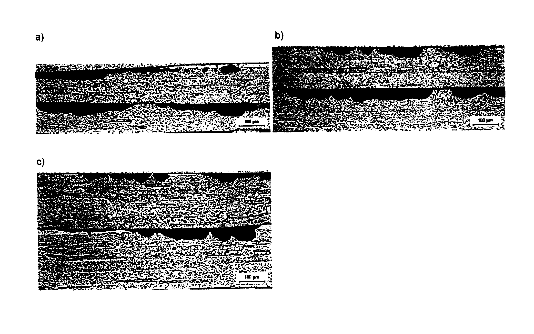
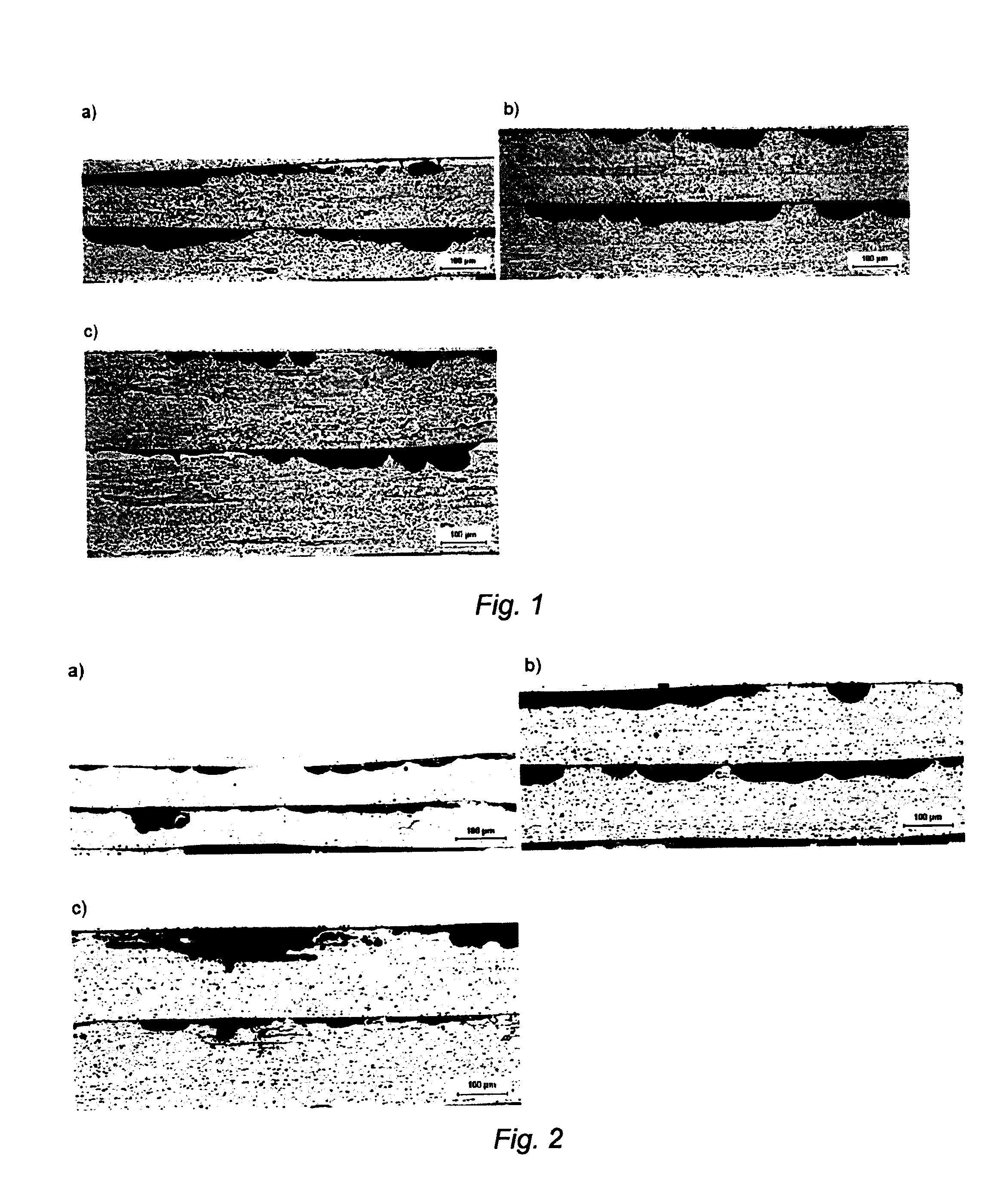
[0110]The thickness of the interlayer is one parameter that needs to be controlled in order to provide the desired result. A too thin interlayer cladding will naturally not supply sufficiently good properties after brazing. A too thick interlayer cladding will act essentially as a core without any interlayer and the likelihood for pitting corrosion will increase drastically, and may even reduce the corrosion resistance of the brazed product. In other words, if the interlayer is too thick, the advantages obtainable by the difference in corrosion potential between the core and the interlayer will have less effect on the strip.
[0111]It is important not only to examine the time to perforation but also the propensity by which perforation takes place, e.g. the number of perforations on a given sample size and the general corrosion morphology. Typically, a lateral corrosion morphology with general surface attack is beneficial whereas pitting and intergr...
example 3
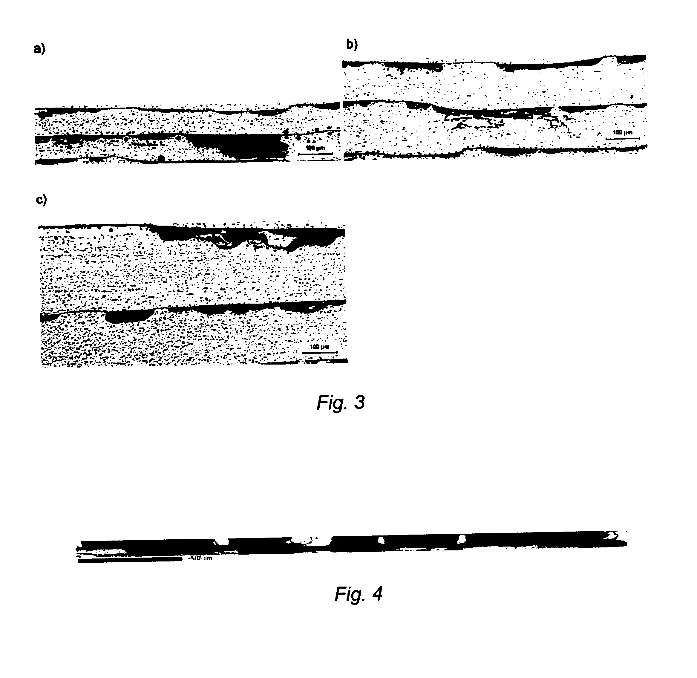
[0114]A brazing sheet with the material combination according to alloy combination 7 in Table 2 was prepared according to the experimental details described above. After brazing the material was mounted in the longitudinal direction, ground and very finely polished and elecropolished to facilitate good surfaces for EBSD measurement. The recrystallization texture of the interlayer was measured with EBSD. All in all 150 mm of interlayer length was examined in order to ensure good statistics for the texture analysis.
[0115]The interlayer withstood the molten filler penetration excellently with little dissolution, and the grains in the interlayer were large. It was found that a {110} texture dominated the interlayer and a volume fraction of 61% was obtained. The mean grain size of the material with this texture was 302 μm. In FIG. 4 the interlayer is depicted with the grains with the {110} texture filled in with black colour, and the grains with all other texture components filled in wit...
PUM
| Property | Measurement | Unit |
|---|---|---|
| Grain size | aaaaa | aaaaa |
| Temperature | aaaaa | aaaaa |
| Temperature | aaaaa | aaaaa |
Abstract
Description
Claims
Application Information