
Chromatographic material and methods for the synthesis thereof

a technology of chromatographic material and synthesis method, which is applied in the field of chromatographic sample separation, can solve the problems of irreversible retention of solutes on the stationary phase, relatively low sample capacity of the bed of non-porous particles, etc., and achieve excellent ph resistance, improved thermal stability, and high mechanical robustness

Inactive Publication Date: 2015-08-13
THERMO ELECTRON MFG +1
View PDF3 Cites 8 Cited by
  • Summary
  • Abstract
  • Description
  • Claims
  • Application Information

AI Technical Summary

Benefits of technology

The present invention relates to the use of nanometer sized parts, called silsesquioxanes, to make porous or non-porous materials for chromatographic applications. These materials have excellent resistance to pH and high mechanical strength, and are more stable at different temperatures and pH levels compared to existing materials. The use of silsesquioxanes offers a greener synthetic process and a variety of high-performance separation media.

Problems solved by technology

A bed of non-porous particles has a relatively low sample capacity.
Without pH control both of these processes may lead to irreversible retention of solutes on the stationary phase.

Method used


Image

  • Chromatographic material and methods for the synthesis thereof
  • Chromatographic material and methods for the synthesis thereof
  • Chromatographic material and methods for the synthesis thereof

Examples


example 1

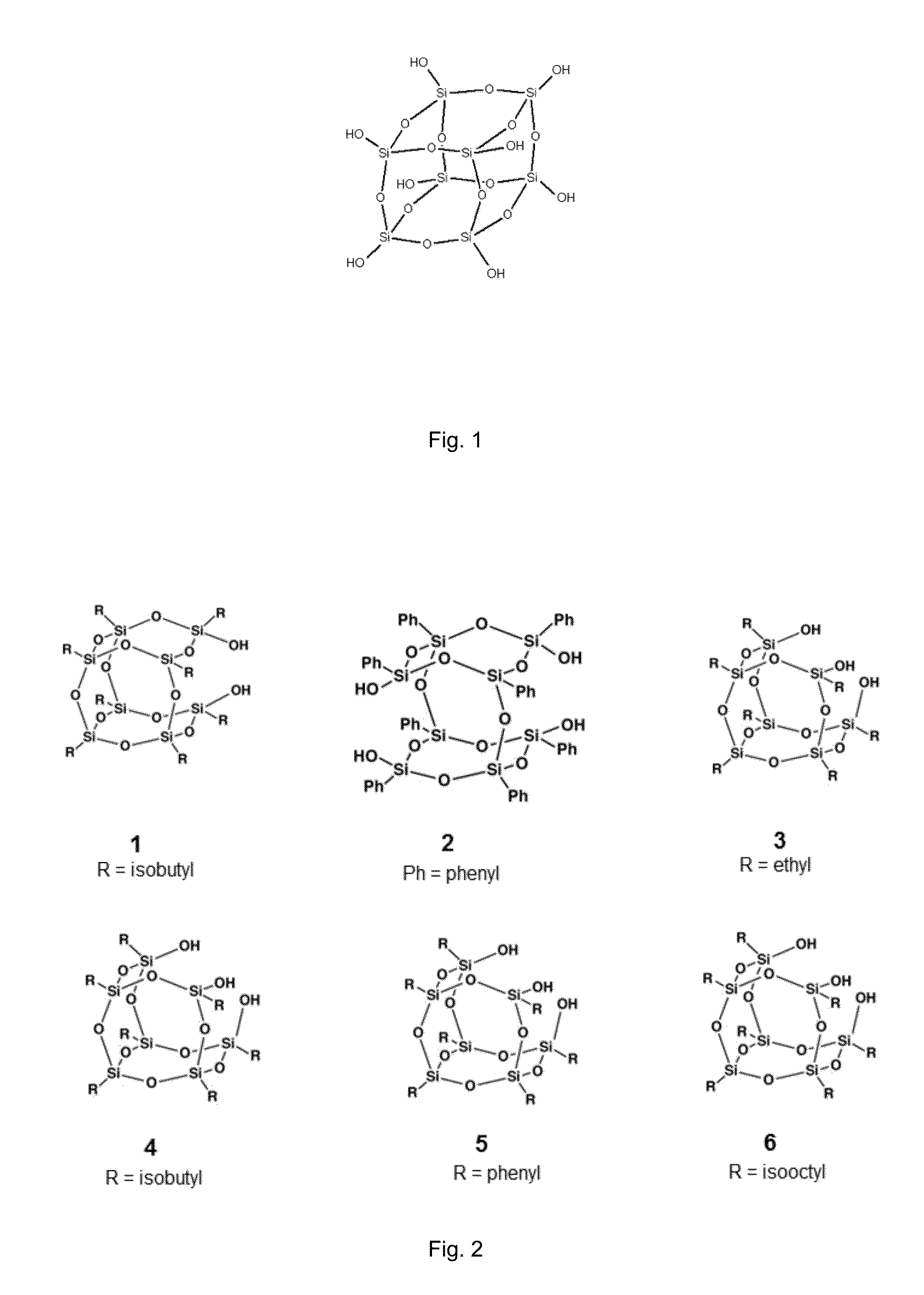
[0093]The reaction followed the general procedure described above but with a slight variation. The TEOS and POSS were dissolved in ethanol prior to addition to the hydrolysis solution. For this, a volume of ethanol equal to four times the volume of the combined precursors was used (i.e. 3.56 ml TEOS and 0.44 ml POSS (4 ml total) were dissolved in 16 ml of ethanol), which was taken from the total ethanol content (i.e. 384 ml instead of 400 ml of ethanol was mixed with 250 ml DI H2O to constitute the hydrolysis solution). The rationale behind this is that at least the TEOS diffusion into the hydrolysis solution is significantly aided by dilution prior to mixing under traditional Stöber conditions. Therefore, the decision was taken to dissolve the precursors prior to mixing.

example 2

[0094]In Example 2, the procedure of Example 1 was followed but the amounts of precursors were changed so that a 1:1 mixture was achieved. Therefore, Example 2′s composition was 2 ml TEOS and 2 ml POSS. Both Examples 1 and 2 produced spherical particles with a wider particle size distribution normally associated with silica particles obtained under modified Stöber conditions. Both Examples 1 and 2 produced silica with high %C composition after synthesis (see results below).

examples 3-6

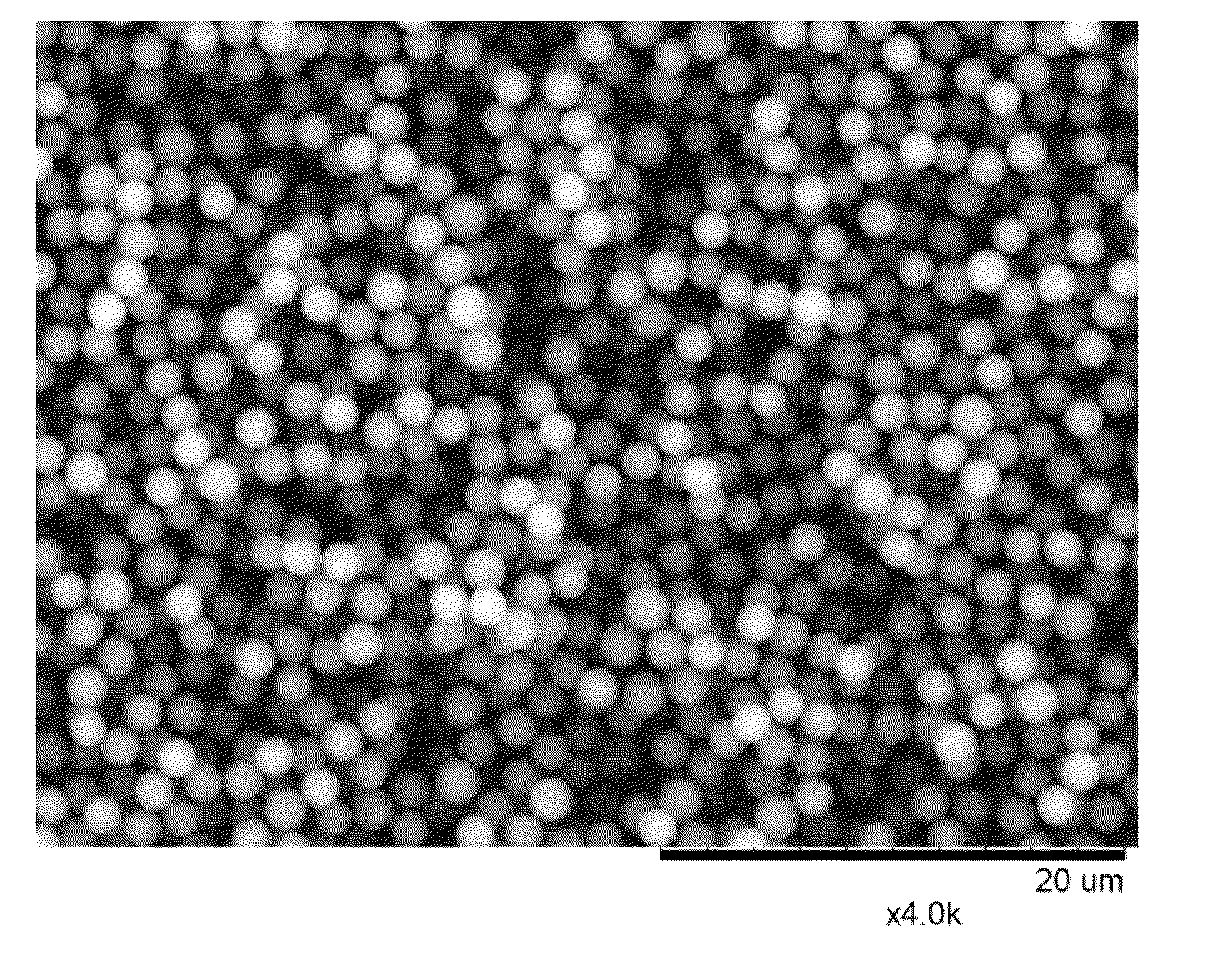
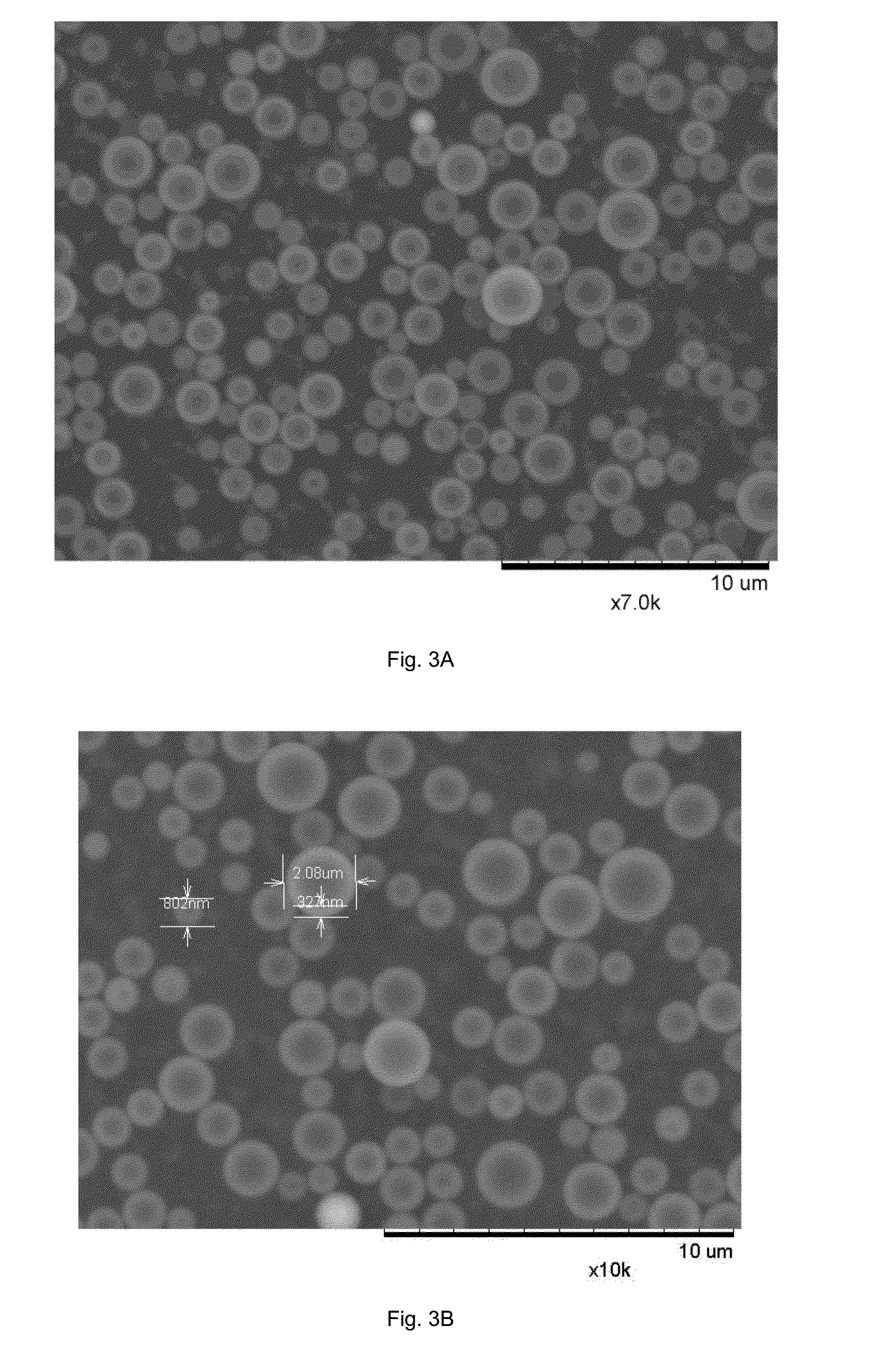
[0095]Examples 3-6 were focused on improving the resultant particle size distribution. The experimental protocol reverted back to the general procedure first described above, i.e. in these cases no pre-dilution of the precursors was performed. The TEOS and POSS reagents were mixed together in a glass vial and subjected to ultrasonic mixing for 2 minutes. After which the mixed precursors solution was added to the reaction flask. These Examples produced particles with a very narrow particle size distribution and mean particle diameter of ˜1.5 μm. Without being bound by any theory, it is believed that the alkyl, in these examples isooctyl, chains in the POSS compound, when added to the reaction mixture, help to stabilise the reaction medium, thereby allowing a stable emulsion to be formed and preventing serious particle aggregation. The %carbon composition was consistent with the results obtained from Example 1.


PUM

PropertyMeasurementUnit
median particle diameteraaaaaaaaaa
BET specific surface areaaaaaaaaaaa

Abstract

A particulate material for chromatographic use comprising silica particles is provided having a skeleton structure containing silsesquioxane cage moieties. The material is useful as a chromatographic material, for example in HPLC. The silica particles may be hybrid organo-silica particles wherein the silsesquioxane moieties comprise a cage structure having silicon atoms positioned at corners of the cage wherein one or more silicon atoms positioned at the corners of the cage carry an organic group. A preferred method of preparing the particulate material comprises hydrolysing a silsesquioxane as a co-component of a hydrolysis mixture, especially in a Stöber or modified Stöber process.

Description

FIELD OF THE INVENTION[0001]This invention relates to the field of chromatographic sample separation that includes liquid chromatography and solid phase extraction and, in particular, it relates to material and the synthesis of material for use as a stationary phase in chromatographic sample separation.BACKGROUND OF THE INVENTION[0002]Liquid chromatography (LC), e.g. HPLC and UHPLC, and solid phase extraction (SPE) are used routinely in both analytical and preparative chromatography applications. In these chromatographic techniques, separation of a sample comprising a mixture of components is achieved by conveying the sample in a liquid mobile phase through a stationary phase in a column, thereby causing the sample to separate into its components due to different partitioning between the mobile and stationary phases of each of the components (i.e. the components have different partition coefficients). The stationary phase is typically in the form of a bed of particles packed within ...

Claims


Application Information

Patent Timeline
Patent Type & Authority Applications(United States)
IPC IPC(8): B01J20/283B01J20/22B01J20/30B01J20/28B01J20/10
CPCB01J20/283B01J2220/42B01J20/28085B01J20/28059B01J20/28061B01J20/28016B01J20/28004B01J20/28019B01J20/103B01J20/3085B01J20/3071B01J20/3078B01J20/22B01J2220/44B01J20/28083B01J20/10B01J20/287B01J2220/80B01J2220/82B01J2220/825B01J20/28057B01J20/28078B01J20/28
Inventor SKINLEY, KEVINLIU, XIAODONGPOHL, CHRISTOPHER A.RITCHIE, HARALD
Owner THERMO ELECTRON MFG
Learn More