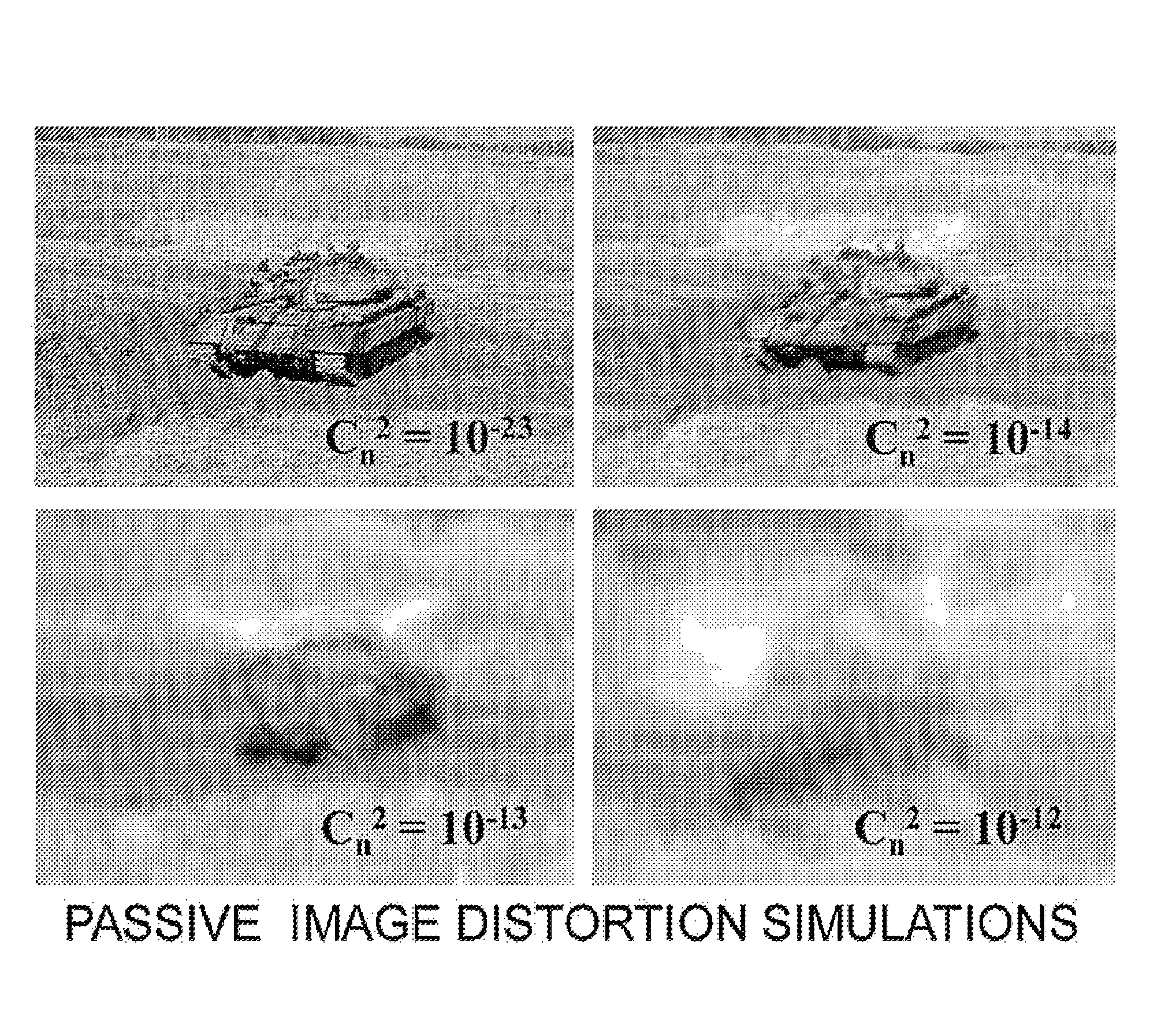
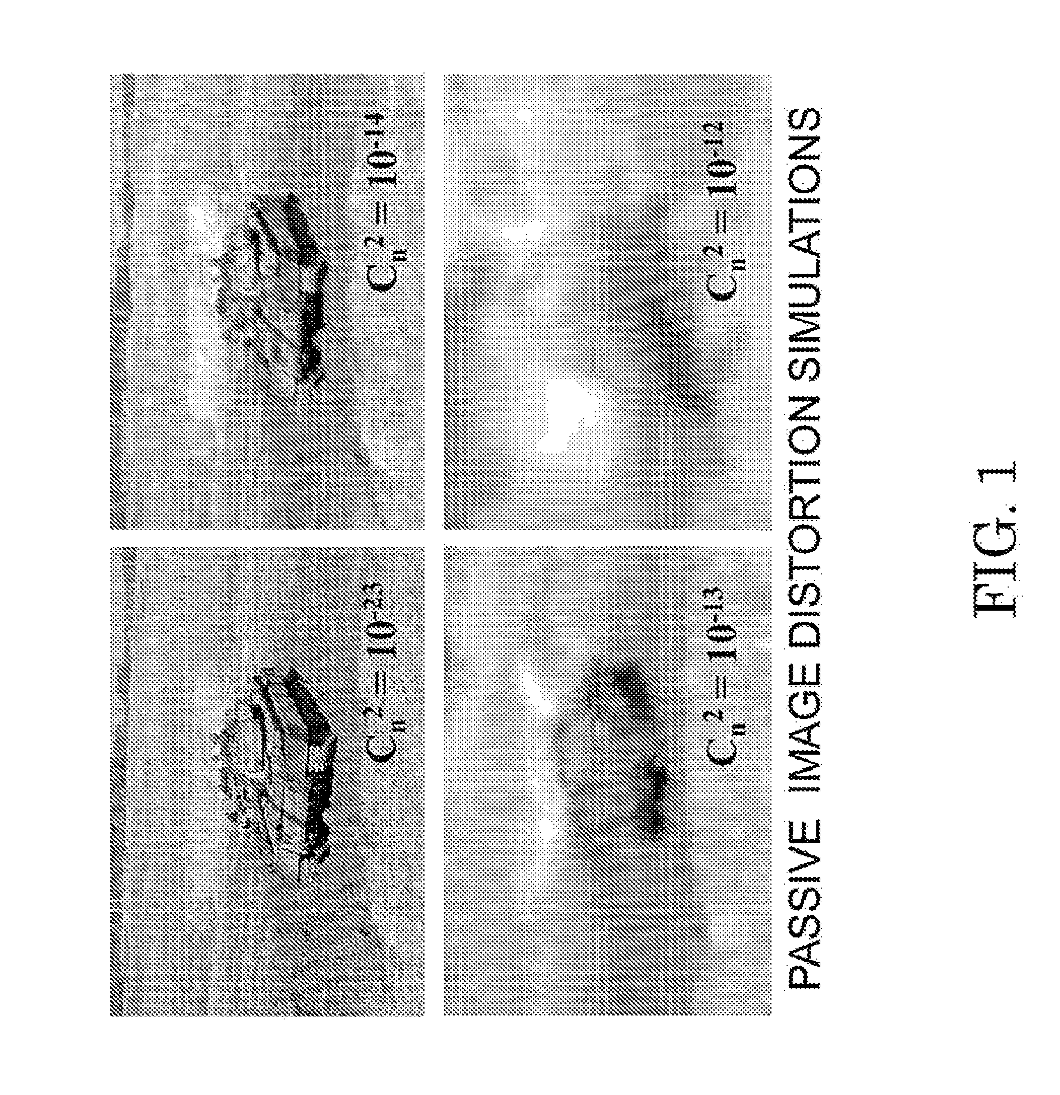
Optical signals passing through a time varying inhomogeneous medium, such as the Earth's lower
atmosphere, can become significantly distorted when propagating over ranges of even as short as several hundred meters.
Thirdly, point sources separated by angular distances exceeding a characteristic value (the isoplanatic angle) appear to wander independently.
Ground-to-ground imaging-through-turbulence problems essentially involve image blur, which is caused primarily by turbulence close to the
system receiving aperture, and image
distortion, which is due to turbulence weighted toward the target object that is under observation by the
system.
Unfortunately, there are several problems with the use of guide
stars.
First, a
guide star approach is not a passive solution.
Active systems that require the illumination of a target scene prior to detection of significant targets are not stealthy and are undesirable in most tactical situations that are of interest in a military situation.
Second, many imaged objects may not have useful reflective properties that will work properly with an illumination
beacon.
Other alternatives, such as placing an illuminator in the object plane, requiring objects of interest to
mount glint reflectors, or forming
laser-induced
fluorescence (LIF) guide
stars on target surfaces are obviously not practical from an Army application standpoint.
Thus the guide star method is not optimized to produce a useful result for removing turbulent blur.
First, the turbulence that is causing the most image blur is close to the sensing aperture.
Second, scene elements that are separated in the scene by a significant angular separation experience anisoplanatic effects limiting the ability of a system to correct turbulent image perturbations at large angular separation from the guide star.
This effect impairs the performance of guide-star-based systems, because turbulent perturbations on the guide star
wavefront in one part of the
image frame are not the same turbulent perturbations that
impact scene elements in another part of the
image frame.
Guide-star-based systems thus do not do well at correcting for turbulent blur in different parts of an imaged scene, underscoring the need for a
passive method that can correct for turbulence sequentially in different parts of the image.
In particular, source points present on surfaces that are rough on the order of a single
wavelength of the propagating
radiation, will not produce a single coherent source even in a
point source sense.
Unfortunately, for many terrestrial (ground-to-ground) imaging scenarios the probability of obtaining any portion of an image that is free of significant turbulence may be so small as to provide a negligible chance of obtaining a set of null-turbulence patches sufficient to construct an unperturbed image.
A 24:139-155 (2007)] present at the system aperture gives rise to a problem.
That problem is a limitation on how frequently a given mode may be corrected given a specific rate of image collection by the optical system, in combination with the strength of aberration due to a specific mode.
The limitation of this approach is the high number of image samples to be collected rapidly enough (several thousand sample images per second) to track the evolving state of the various perturbation
modes.
This is because the method is relatively inefficient, relying on a stochastic adjustment procedure.
Because the maximum sampling rate of an image at an adequate
signal-to-
noise ratio is limited by the amount of ambient light available to produce the image and the system's light gathering capability, sufficiently high frame rates may not be possible without the augmentation of the system by a
high intensity light source in the imaged scene to provide the necessary illumination.
This amenity may not be available in military or in many other contexts.

