Single-crystal piezoelectric fiber composite and magnetoelectric laminate composite including the same

a single-crystal piezoelectric fiber and composite technology, applied in the field of single-crystal piezoelectric fiber composite and magnetoelectric laminate composite including the same, can solve the problems of difficult to predict and design the control and operation of devices, operate devices including such composites, and impose limitations on application into various shapes and usages, etc., to achieve improved piezoelectric properties, improved piezoelectric properties, and high mechanical stability

Active Publication Date: 2015-08-20
KOREA INST OF MATERIALS SCI
View PDF1 Cites 13 Cited by
  • Summary
  • Abstract
  • Description
  • Claims
  • Application Information

AI Technical Summary

Benefits of technology

[0013]Accordingly, the present invention has been made keeping in mind the above problems encountered in the related art, and an object of the present invention is to provide a piezoelectric fiber composite and a preparation method thereof, wherein the piezoelectric fiber composite includes piezoelectric fibers composed of a single crystal having a specific crystallographic direction oriented in a poling direction to maximize piezoelectric effects; and a magnetoelectric laminate composite and a manufacturing method thereof, wherein the magnetoelectric laminate composite includes the piezoelectric fiber composite as above and a magnetostrictive layer formed of a magnetostrictive material on one or both sides of the piezoelectric fiber composite to achieve greatly improved magnetoelectric effects due to interactions with the composite.
[0019]According to the present invention, a piezoelectric fiber composite includes piezoelectric fibers composed of a single-crystal piezoelectric material and arranged so that the <011> direction of the single crystal is identical to the thickness direction of the composite and the <001> direction of the single crystal is identical to the longitudinal direction of the composite, thus exhibiting superior piezoelectric strain properties and sensing properties depending on a specific orientation direction of the piezoelectric single crystal. In particular, upon operation in 32 mode at which a poling direction and a strain direction are perpendicular to each other, the composite of the invention can manifest remarkably improved piezoelectric properties, and thereby can be useful in not only sensors and actuators but also energy harvesting devices for mechanical vibration energy due to high mechanical stability.
[0020]Also, according to the present invention, a magnetoelectric laminate composite is configured such that a magnetostrictive layer composed of a magnetostrictive material such as nickel (Ni) or Metglas (FeBSi alloy) is provided on one or both sides of the piezoelectric fiber composite having the properties as above, thus ensuring significantly improved magnetoelectric properties compared to existing magnetoelectric laminate composites. Furthermore, this laminate can show excellent performance in energy harvesting devices in response to external stimulation including changes in mechanical vibration and / or magnetic field.
[0021]In particular, when the magnetoelectric laminate composite according to the present invention is used as an energy harvesting device for power-line monitoring sensor driving power source, power is supplied to the sensor via energy harvesting for producing power from a parasitic magnetic field around the power-line and / or mechanical vibration energy around the power-line. Thereby, as power can be continuously and stably supplied without the need for periodic replacement of a power supply, a sensor node can be operated semi-permanently, and simultaneously the lifecycle of the sensor node and the reliability of data to be sensed can be increased, ultimately accelerating the commercialization of USN-based systems such as power-line remote monitoring systems.

Problems solved by technology

However, most piezoelectric materials are ceramic materials, and thus limitations are imposed on application into various shapes and usages thereof due to the intrinsic brittleness of ceramic materials.
However, since a piezoelectric fiber composite such as MFC includes the polymer matrix between electrodes and piezoelectric fibers, it is difficult to predict and design the control and operation of devices; furthermore, high driving voltage is required to operate the device including such a composite, which is very undesirable.
Moreover, a piezoelectric fiber composite such as MFC is problematic because it is impossible to maximize piezoelectric properties that vary depending on the crystal orientation of the piezoelectric material, due to the use of ceramic piezoelectric fiber materials.

Method used


Image

  • Single-crystal piezoelectric fiber composite and magnetoelectric laminate composite including the same
  • Single-crystal piezoelectric fiber composite and magnetoelectric laminate composite including the same
  • Single-crystal piezoelectric fiber composite and magnetoelectric laminate composite including the same

Examples


example 1

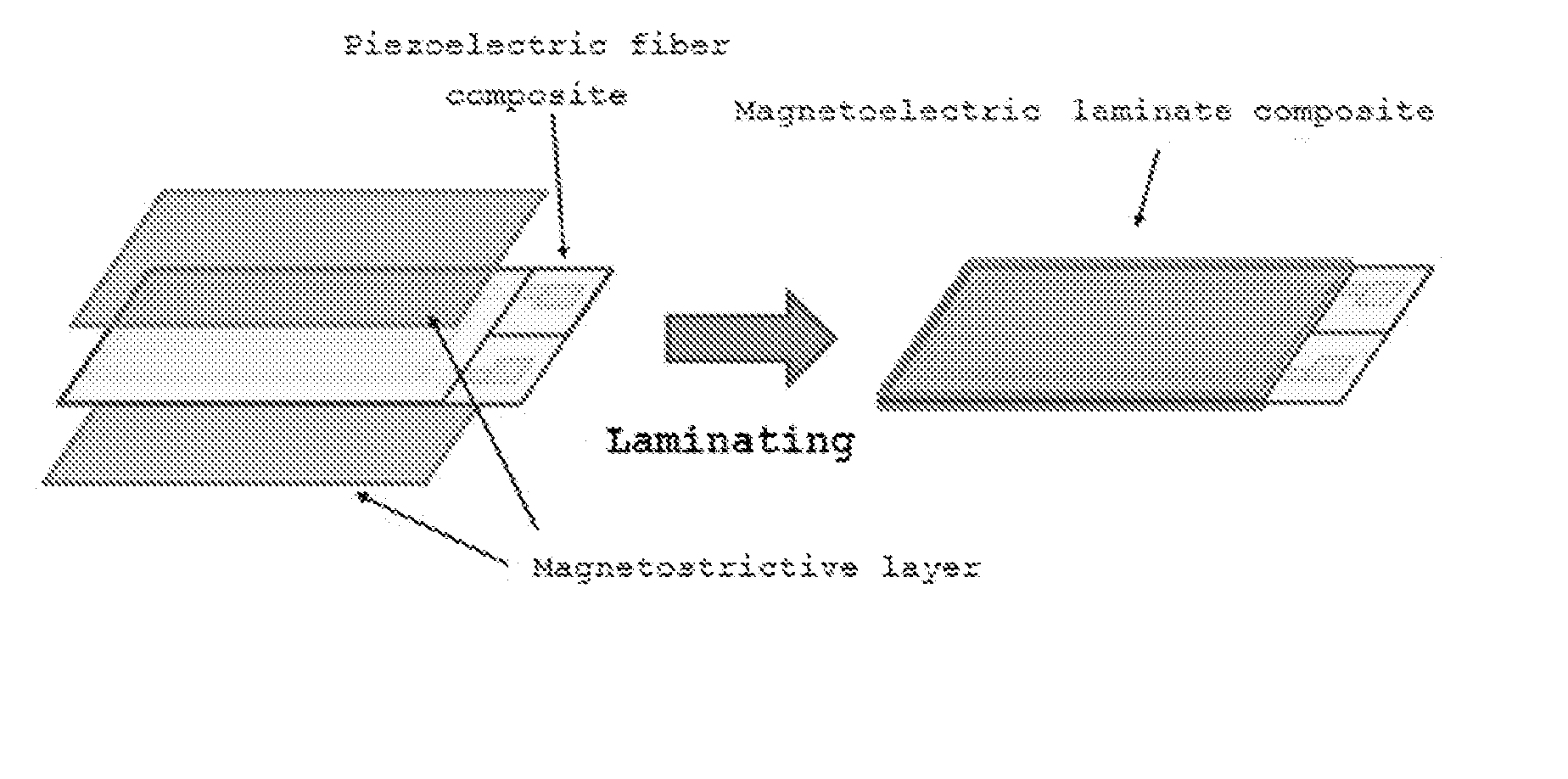
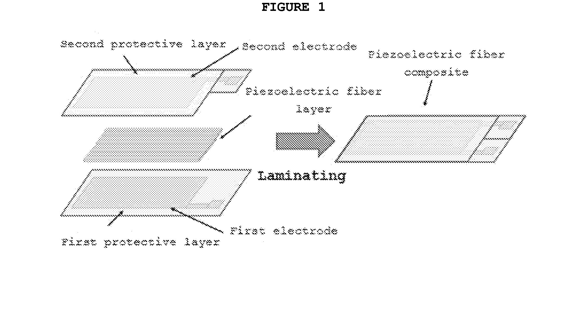
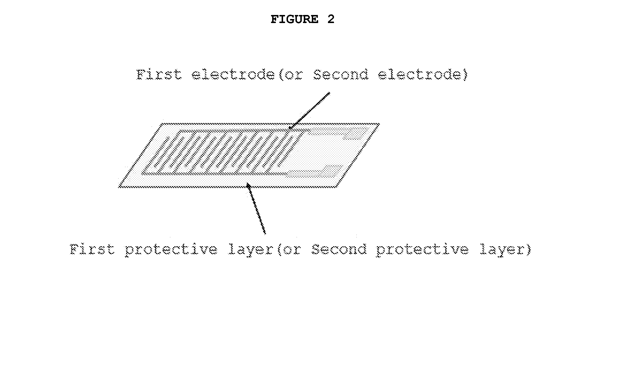
[0095]A PMN—PZT single-crystal sheet having a rhombohedral perovskite structure where a thickness direction was oriented in [011] and a transverse orientation was d32 mode (longitudinal direction: [100], width direction: [011]) was mechanically machined so as to have a thickness of about 200 μm, after which the machined piezoelectric single-crystal sheet was bonded on a PI film having a Cu full-area electrode plated on one side thereof. Subsequently, the piezoelectric single-crystal sheet was cut to a longitudinal direction of the PI film, thus forming a piezoelectric fiber layer including one or more piezoelectric single-crystal fibers with a width of about 200 μm. Subsequently, another PI film having a Cu full-area electrode plated on one side thereof was bonded on the piezoelectric fiber layer using epoxy resin and poling was then performed at an electric field of 1 kV / mm, thereby obtaining a piezoelectric fiber composite.

[0096]Thereafter, a Ni plate having a thickness of about 0...

example 2

[0097]A magnetoelectric laminate composite was manufactured in the same manner as in Example 1, with the exception that a piezoelectric fiber layer was prepared using a PMN—PZT single-crystal sheet having a rhombohedral perovskite structure where a thickness direction was oriented in [011] and a transverse orientation was d31 mode (longitudinal direction: [011], width direction: [100]).

example 3

[0098]A magnetoelectric laminate composite having a structure illustrated in FIG. 3B was manufactured in the same manner as in Example 1, with the exception that a Ni plate was bonded on both sides of the piezoelectric fiber composite.


PUM

PropertyMeasurementUnit
AC magnetic fieldaaaaaaaaaa
piezoelectricaaaaaaaaaa
thicknessaaaaaaaaaa

Abstract

A piezoelectric fiber composite and a magnetoelectric laminate composite including the same are disclosed. The piezoelectric fiber composite includes a first protective layer having a first electrode, a second protective layer having a second electrode, and a piezoelectric fiber layer formed between the first and the second electrode and having piezoelectric fibers arranged in the longitudinal direction of the composite, wherein the piezoelectric fibers include a single-crystal piezoelectric material and are configured such that a <011> direction of the single crystal is identical to a thickness direction of the composite and a <001> direction of the single crystal is identical to a longitudinal direction of the composite, thus exhibiting superior piezoelectric strain properties and sensing properties. Also, the magnetoelectric laminate composite includes the piezoelectric fiber composite and a magnetostrictive layer including a magnetostrictive material such as nickel (Ni) or Metglas (FeBSi alloy), thus ensuring significantly improved magnetoelectric properties.

Description

CROSS-REFERENCE TO RELATED APPLICATION[0001]This application claims priority to Korean Patent Application No. 10-2014-0010569 filed on Jan. 28, 2014 and all the benefits accruing therefrom under 35 U.S.C. §119, the contents of which are incorporated by reference in their entirety.BACKGROUND OF THE INVENTION [0002]1. Field of the Invention[0003]The present invention relates to a piezoelectric fiber composite, a preparation method thereof, a magnetoelectric laminate composite including the piezoelectric fiber composite, a manufacturing method thereof and a piezoelectric device including the piezoelectric fiber composite or the magnetoelectric laminate composite. More particularly, the present invention relates to a single-crystal piezoelectric fiber composite containing single-crystal piezoelectric fibers oriented in a specific direction, a preparation method thereof, a magnetoelectric laminate composite including the piezoelectric fiber composite, a manufacturing method thereof, and ...

Claims


Application Information

Patent Timeline
Patent Type & Authority Applications(United States)
IPC IPC(8): H01L41/12H01L41/083B32B38/00H01L41/053B32B37/18H01L41/08H01L41/047
CPCH01L41/125H01L41/082H01L41/083H01L41/047B32B2457/00B32B37/18B32B38/0004B32B2307/20H01L41/0533H02N2/18Y10T156/1052H10N30/00H10N30/1061H10N30/85H10N35/101H10N30/50H10N30/87H10N30/883
Inventor RYU, JUNGHOPARK, DONG-SOOYOON, WOON-HA
Owner KOREA INST OF MATERIALS SCI
Why Eureka
Try Eureka