Reactor vessel, system and method for removiing and recovering volatilizing contaminants from contaminated materials

a technology reactor vessels, which is applied in the direction of special form destructive distillation, coking carbonaceous materials, separation processes, etc., can solve the problems of affecting the yield of volatilizing organic compounds, hazardous materials, and hazardous materials, and achieve the effect of reducing temperature requirements, increasing relative volatility of key hydrocarbon components, and increasing the yield of recovered organic compounds

Active Publication Date: 2015-08-27
OSS MANAGEMENT SERVICES PTY
View PDF1 Cites 2 Cited by
  • Summary
  • Abstract
  • Description
  • Claims
  • Application Information

AI Technical Summary

Benefits of technology

[0032]The inverter may include a semi-conductor relay which is configured as an H-bridge. The H-bridge may include four legs, each associated with a switch. The output circuit may be connected across the center of the H-bridge. When the relevant two switches are closed, current may flow through the load in one direction. When the same switches are opened and the opposing two switches closed, current may be allowed to flow in the opposite direction. By precisely timing the opening and closing of the switches, it is possible to sustain oscillations in the load circuit. This is fed to the external induction coil whereupon mutual inductance between the external induction coil and the reactor vessel (and the internal induction coil inside the vessel, if it is present) creates a magnetic coupling. This induction causes eddy currents to be induced into the reactor vessel from the external induction coil around the reactor vessel and the internal induction coil in the blind tube in the center of the reactor vessel.
[0033]The system also may include a vacuum, not only so as to increase relative volatility of key hydrocarbon components in a contaminated load, thus creating a higher yield in recovered hydrocarbons, but also to reduce the temperature requirements under which the system would otherwise function. Operating the system under vacuum conditions reduces running costs, increases distillation of hydrocarbon fractions, and reduces cycle times.

Problems solved by technology

For example, underground gasoline tanks may leak or solvents used in industrial processes may be discharged illegally into waste water or sumps or directly onto the ground.
In any case, the hazardous material, typically a volatilizing organic compound, may propagate great distances through the ground and even enter ground water aquifers.
It will be appreciated that the resulting environmental impact may be devastating.
Many hazardous materials found at these sites are stable, do not undergo environmental degradation at reasonably fast rates, have high boiling points and are considered toxic at very low concentration levels.
Known techniques, however, suffer from a range of shortcomings.
One such shortcoming is the high costs associated with removing and cleaning contaminated soil by means of commercially available techniques and systems, because of the inherent characteristics and operating parameters of these techniques and systems.
Another shortcoming is that known treatment techniques often do not provide an effective solution to the problem, as it is inadequate to remove the hazardous materials completely, leaving behind small amounts of the hazardous materials even in the treated and “cleaned” soil, which continues to be a potential source of an environmental disaster.
Also, with known soil cleaning techniques often only a limited volume of ground soil can be treated at a time.
This limitation not only increases costs as a result of repeated cleaning cycles, as well as with respect to the need for safe storage and transport of contaminated soil, but also increases the time that it takes to clean a contaminated area sufficiently.
A further disadvantage of many treatment options is that the contaminated materials are heated to temperatures which vaporise and / or thermally destroy the contaminants.
These processes do not allow for the recovery and / or potential re-use of the contaminants.

Method used


Image

  • Reactor vessel, system and method for removiing and recovering volatilizing contaminants from contaminated materials
  • Reactor vessel, system and method for removiing and recovering volatilizing contaminants from contaminated materials
  • Reactor vessel, system and method for removiing and recovering volatilizing contaminants from contaminated materials

Examples


Embodiment Construction

[0051]The reactor vessel of the invention will now further be described by way of non-limiting example only and with reference to the accompanying drawings in which—

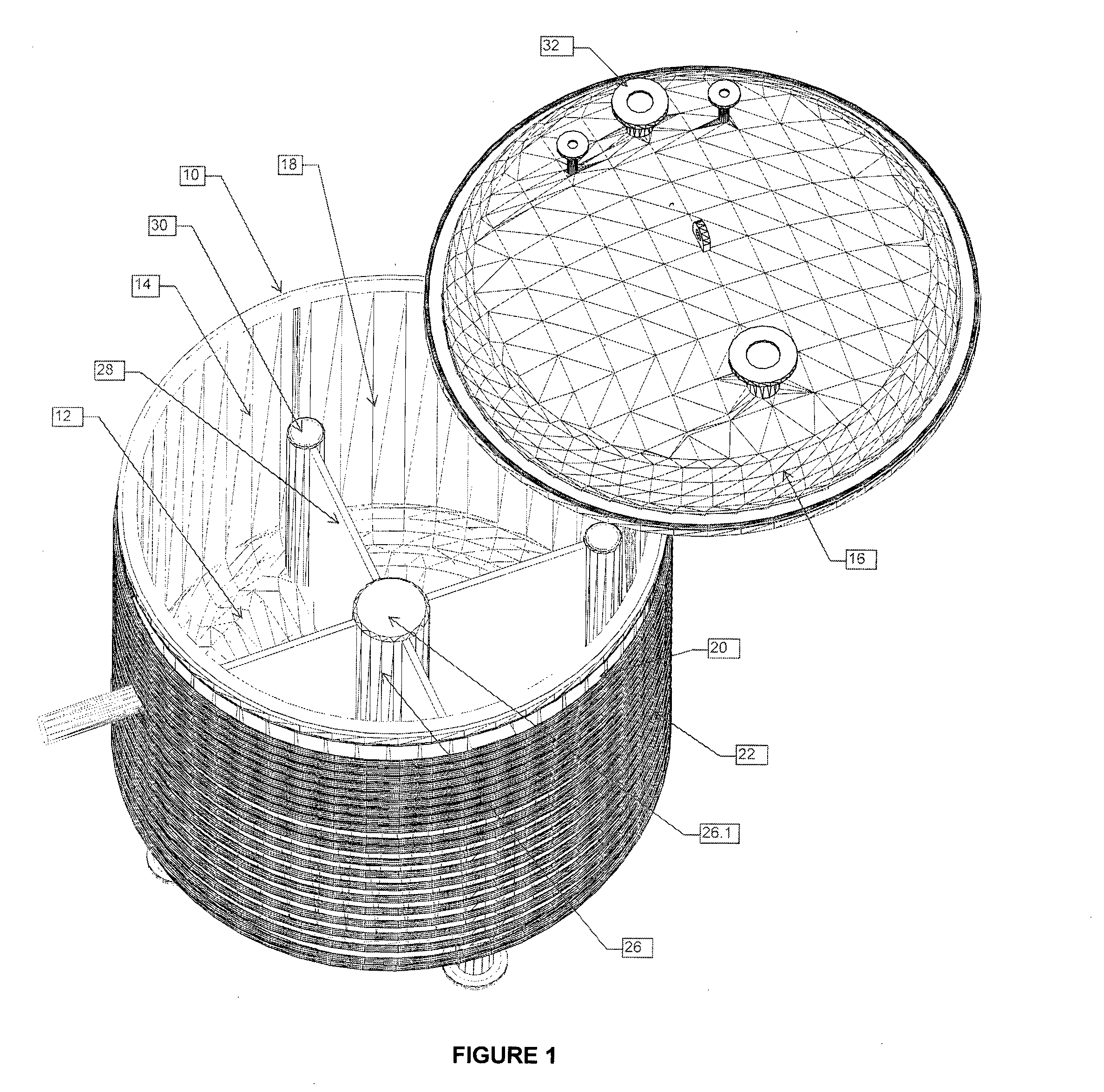
[0052]FIG. 1 is a perspective view of a reactor vessel according to one embodiment of the invention, the reactor vessel being illustrated with its removable lid in a partially open position, and including a blind tube and four conducting plates;

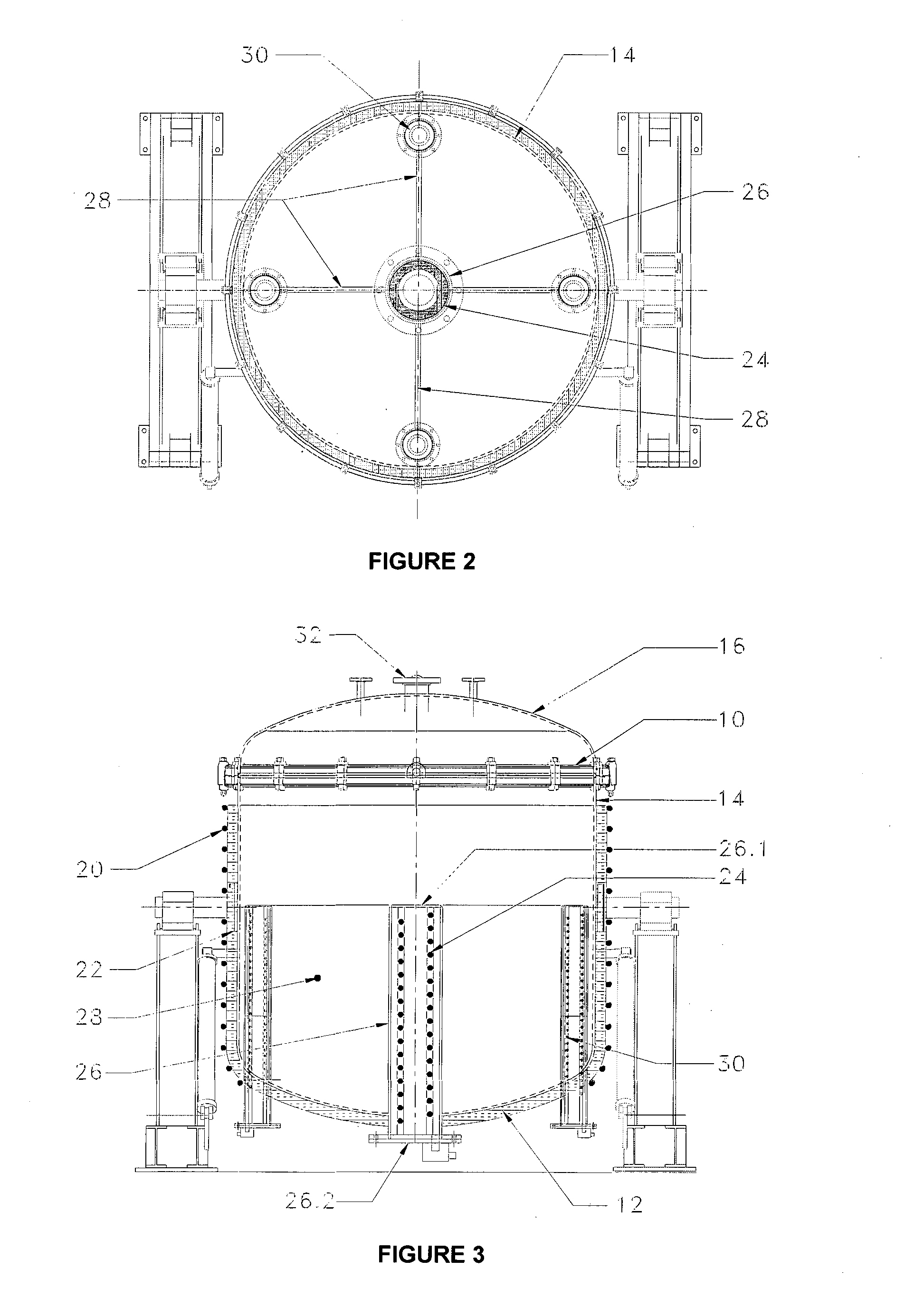
[0053]FIG. 2 is a plan view from above of the reactor vessel of FIG. 1, with the lid removed; and

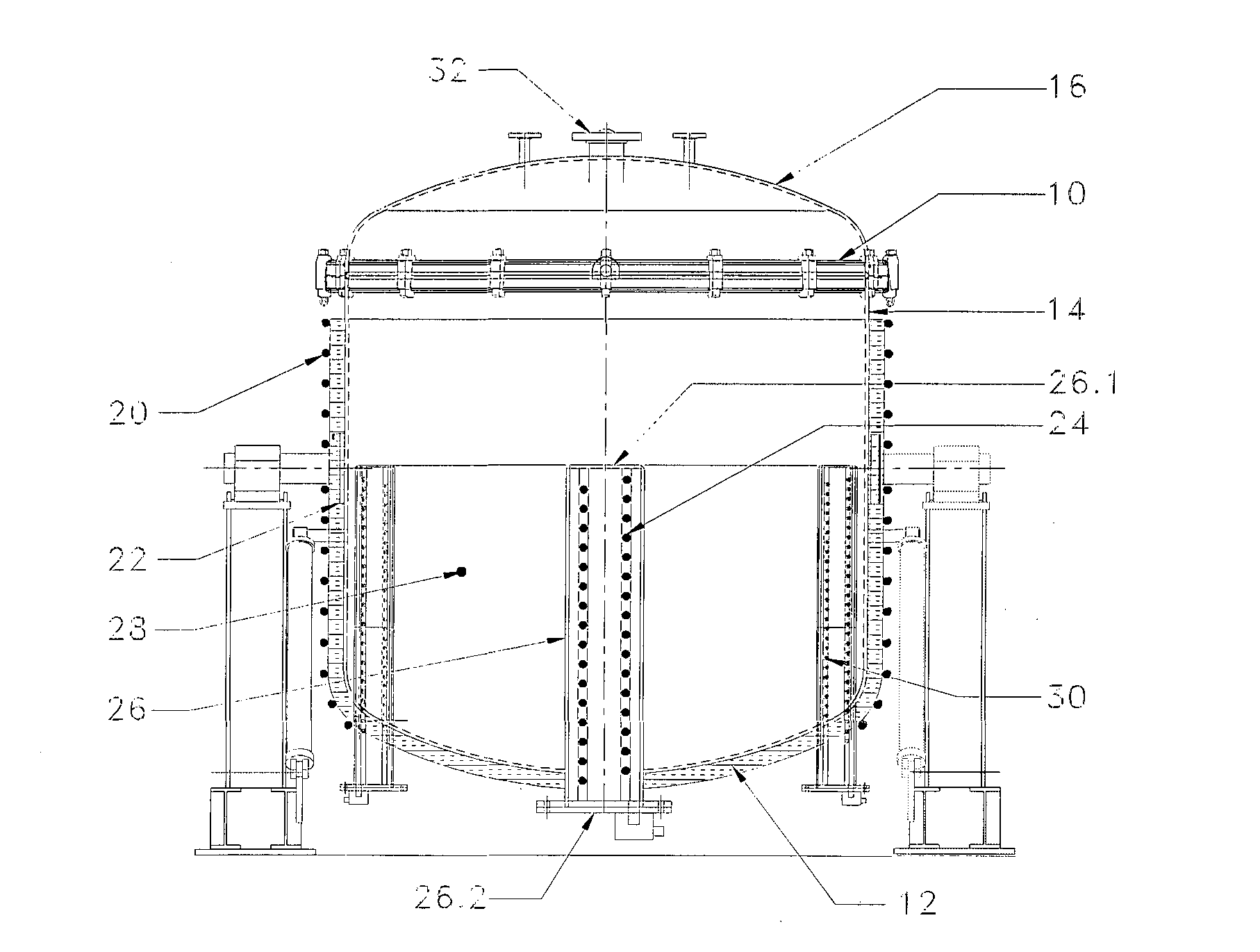
[0054]FIG. 3 is a cross-sectional side view of the reactor vessel of FIG. 1, with the lid in a closed position.

[0055]An insulated, magnetic, electrically conductive reactor vessel according to the invention is designated by reference numeral [10]. The reactor vessel [10] comprises a reactor base [12]; a cylindrical reactor wall [14] extending upright from the base [12]; and a removable lid [16] dimensioned to rest on the cylindrical reactor wall [14] for sealing the reactor vessel [10]...


PUM

PropertyMeasurementUnit
frequencyaaaaaaaaaa
frequencyaaaaaaaaaa
temperaturesaaaaaaaaaa

Abstract

The invention relates to a reactor, a system and a method for treating and recovery of liquid and / or solid waste materials and by-products from industrial manufacturing and production operations, such as volatilizing organic compounds, by converting these materials into valuable materials which could be recycled and re-used, while at the same time minimizing any residue for final disposal to landfill or incineration. The invention includes an insulated, magnetic, electrically conductive reactor vessel [10] for receiving and treating a contaminated load, the reactor being characterised therein that it is operated under pyrolysis conditions and is heated by radio frequency induction of eddy currents into the reactor vessel [10].

Description

INTRODUCTION[0001]This invention relates to a reactor, a system and a method for on-site and / or off-site treating and recovery of liquid and / or solid waste materials and by-products from industrial manufacturing and production operations, such as volatilizing organic compounds, by converting these materials into valuable materials which could be recycled and re-used, while at the same time minimizing any residue for final disposal to landfill or incineration. Without derogating from the generality of the foregoing, the invention provides for the treatment and recovery of hydrocarbon-containing and contaminated solids, liquids (Newtonian and Non-Newtonian), oil in water emulsions, water in oil emulsions, chlorinated and non-chlorinated solvents, polymeric hydrocarbons, products made from or derived from cellulose, biomass or the like (thus producing the by-product), synthetic gas, pyrolysis oil, water and carbon char. After treatment of these materials, the synthetic gas and pyrolysi...

Claims


Application Information

Patent Timeline
Patent Type & Authority Applications(United States)
IPC IPC(8): C10B19/00C10B1/04
CPCC10B1/04C10B19/00H05B6/129
Inventor BIANCHINA, LEONARD BENJAMINTUNNICLIFFE, IAN NIGEL
Owner OSS MANAGEMENT SERVICES PTY
Why Eureka
Try Eureka