
Electrochemical cell including functionally graded and architectured components and methods

a technology of functional graded and architectured components and cells, applied in the field of electrochemical cells, can solve the problems of limited lifetime, premature failure, drawbacks of conventional cells, etc., and achieve the effect of eliminating costly trial and error in construction and superior properties of designed cells

Active Publication Date: 2015-09-24
SAKTI3
View PDF7 Cites 6 Cited by
  • Summary
  • Abstract
  • Description
  • Claims
  • Application Information

AI Technical Summary

Benefits of technology

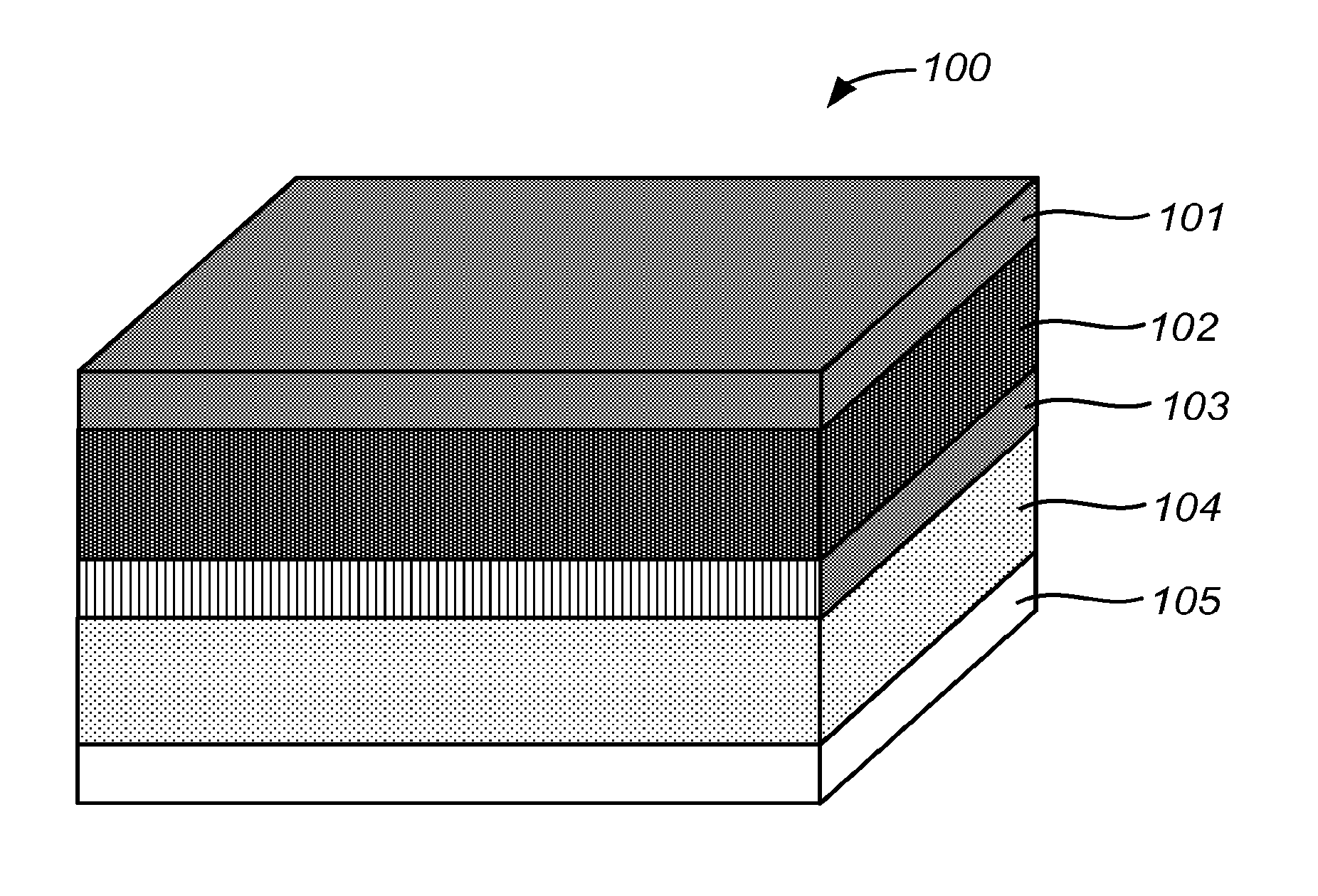
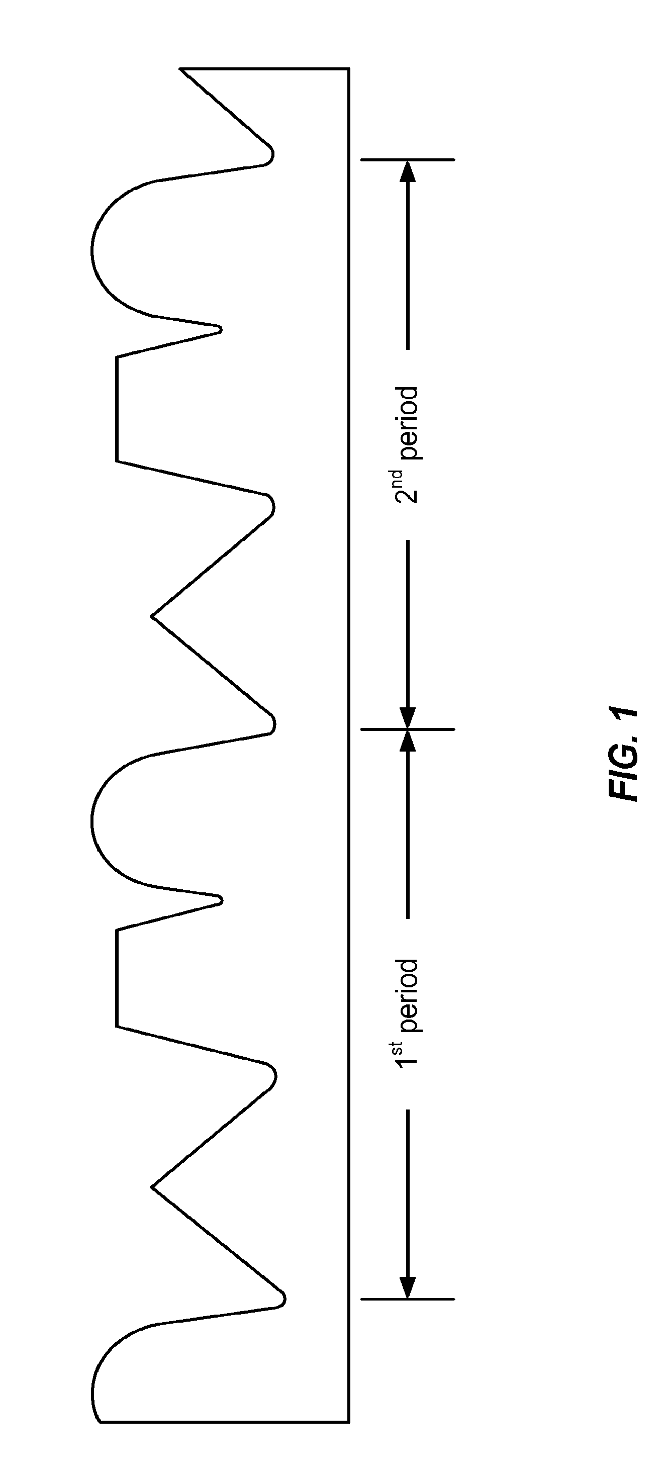
The present invention provides materials and methods for creating electrodes with a microarchitectured morphology that can mitigate intercalation and thermal expansion stresses, strengthen the electrode material. The invention also includes manipulating the materials to form nanocomposite electrodes that neutralize internal stresses, stop crack growth, maximize material strength, and stabilize active material structure. The invention allows for the design and combination of multiple materials in novel arrangements to create electrochemical cells with superior properties and eliminates costly trial and error in construction of prototype cells.

Problems solved by technology

Thus, drawbacks exist with these conventional cells.
The drawbacks include limited lifetime, premature failure, limited storage capability, and other imperfections.
A central challenge to create cost-effectively microarchitectured and functionally graded electrodes, cells or batteries is precisely tuning material properties for the specific role of that material needed.
However, such a process is too costly and can not be used for mass production of high-tech electrochemical cells.

Method used


Image

  • Electrochemical cell including functionally graded and architectured components and methods
  • Electrochemical cell including functionally graded and architectured components and methods
  • Electrochemical cell including functionally graded and architectured components and methods

Examples


example 1

A Functionally Graded Electrode and its Manufacturing Technique

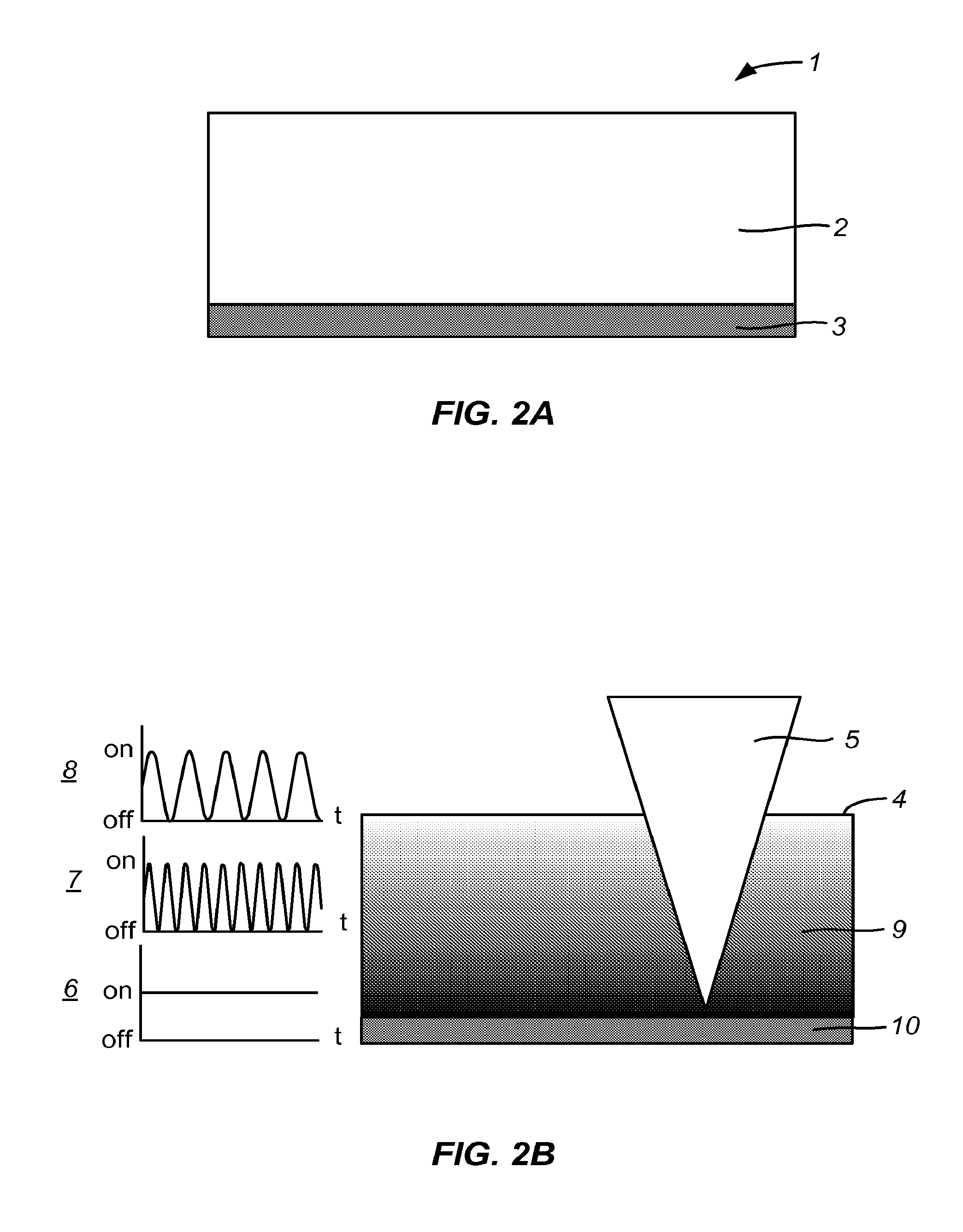
[0046]In FIGS. 2A and 2B, a functionally graded graphite anode is created by focusing a laser beam through polymer electrolyte layer by layer gradually from current collector to some desired distance toward the surface of the polymer electrolyte with decreasing the frequency of turning on-and-off the laser beam as the focus point of the laser beam is gradually moved away from the current collector. The electrode 1 comprises of polymer electrolyte (LiPF6 plus polyethyleneoxide, PEO) 2 coated on top of copper current collector 3 as detailed described in FIG. 2A. Because of the high-energy of the Nd:YAG laser beam 4, the polymer in polymer electrolyte, where the laser beam is aimed, will be graphitized as 9 in FIG. 2B. Also, because of decreasing the frequency of turning on-and-off the laser beam (as shown in 6 to 8 in FIG. 2B), the area of graphitized polymer in one layer will be decreased. Hence, concentration of the grap...

example 2

Manufacturing of a Microarchitectured Electrode

[0047]In FIGS. 3A, B, and C, a microarchitectured LiMn2O4 cathode having a periodic but non-arbitrary geometry is made using a silicon (Si) substrate 11 as a template. A Nd:YAG laser 13 is used to machine the substrate and remove material 14, creating a set of channels and ridges that follows a predetermined geometry obtained using a Computer Aided Design (CAD) software as 12. The design is reflecting minimization of intercalation stresses in the LiMn2O4 material according to computer simulations. Once the substrate machining is completed conformal material layers are deposited using physical vapor deposition (PVD) onto the substrate. Respectively, a first titanium (Ti) 18 attachment layer, having a thickness of 50 Å or less, followed by a second aluminum (Al) layer 19, having a thickness of 500 nanometers or higher, to serve as cathode current collector. After deposition of the current collector, the active material (LiMn2O4) 20 is for...

example 3

Manufacturing of a Nanocomposite Material for Electrode

[0048]In FIGS. 4A, B, C, and D, a LiMn2O4 partially stabilized cathode is fabricated by depositing conformal material layers using physical vapor deposition (PVD). The same procedure illustrated here can be used with or without the pre-existence of a substrate 22. In this latter case, the current collector is also serving as substrate material 22. A first layer of LiMn2O4, 23, is deposited having a thickness of 100-500 nanometers. After the first layer is completed a mask, 26, having geometric features of 100 nanometers or higher, is applied onto it and a layer of Li2MnO3, 29, is deposited. Finally the mask is removed and another layer of LiMn2O4, 34, having a thickness of 100-500 nanometers, is deposited to embed the Li2MnO3 features previously created.

[0049]Alternatively to using a mask, sputtering of Li2MnO3 can be employed to create irregular second phase regions on the first layer followed by a layer of LiMn2O4, having a th...


PUM

PropertyMeasurementUnit
thicknessaaaaaaaaaa
sizesaaaaaaaaaa
sizesaaaaaaaaaa

Abstract

Electrochemical cells or batteries featuring functional gradations, and having desirable, periodic configurations, and methods for making the same. One or more methods, in alone or in combination, are utilized to fabricate components of such electrochemical cells or batteries, which are designed to achieve certain thermal, mechanical, kinetic and spatial characteristics, and their effects, singly and in all possible combinations, on battery performance. The thermal characteristics relate to temperature distribution during charge and discharge processes. The kinetic characteristics relate to rate performance of the cells or batteries such as the ionic diffusion process and electron conduction. The mechanical characteristics relate to lifetime and efficiency of the cells or batteries such as the strength and moduli of the component materials. Finally, the spatial characteristics relate to the energy and power densities, stress and temperature mitigation mechanisms, and diffusion and conduction enhancements. The electrochemical cells or batteries constructed according to the methods presented in this invention are useful for all applications that require high rate performance, high energy / power density, good durability, high safety and long lifetime.

Description

CROSS-REFERENCES TO RELATED APPLICATIONS[0001]This application claims priority to U.S. Provisional Patent Application No. 61 / 086,161, filed Aug. 5, 2008, the disclosure of which is hereby incorporated by reference for all purposes.BACKGROUND OF THE INVENTION[0002]The present invention relates generally to electrochemical cells. More particularly, the present invention provides methods and devices having a functionally graded and an architectured component for electrode(s). Merely by way of example, the invention can be applied to a variety of applications including automotive, telecommunication, general energy storage, portable electronics, power tools, power supplies, among others.[0003]As noted, electrochemical cells are used to store energy for a variety of applications. These applications include portable electronics such as cell phones, personal digital assistants, music players, video cameras, and the like. Applications also include power tools, power supplies for military use...

Claims


Application Information

Patent Timeline
Patent Type & Authority Applications(United States)
IPC IPC(8): H01M4/04C23C14/22C23C16/44B29C59/02C23C16/511C23C14/48C23C4/12B29C59/16H01M4/139C23C16/455
CPCH01M4/0404H01M2004/021H01M4/0428H01M4/139H01M4/0426H01M4/0407H01M4/0419H01M4/0471C23C14/22C23C16/44C23C16/45525C23C16/511C23C14/48C23C4/127B29C59/16B29C59/02H01M4/0423B82Y30/00C23C14/025C23C14/042C23C14/08H01M4/13H01M4/131H01M4/134H01M4/382H01M4/505H01M4/70H01M10/0565H01M2004/025H01M10/613H01M10/6554C23C4/134Y02E60/10Y02P70/50H01M6/02
Inventor SASTRY, ANN MARIEALBANO, FABIOWANG, CHIA-WEI
Owner SAKTI3
Learn More