

Perovskite solar cell
- Summary
- Abstract
- Description
- Claims
- Application Information
AI Technical Summary
Benefits of technology
Problems solved by technology
Method used
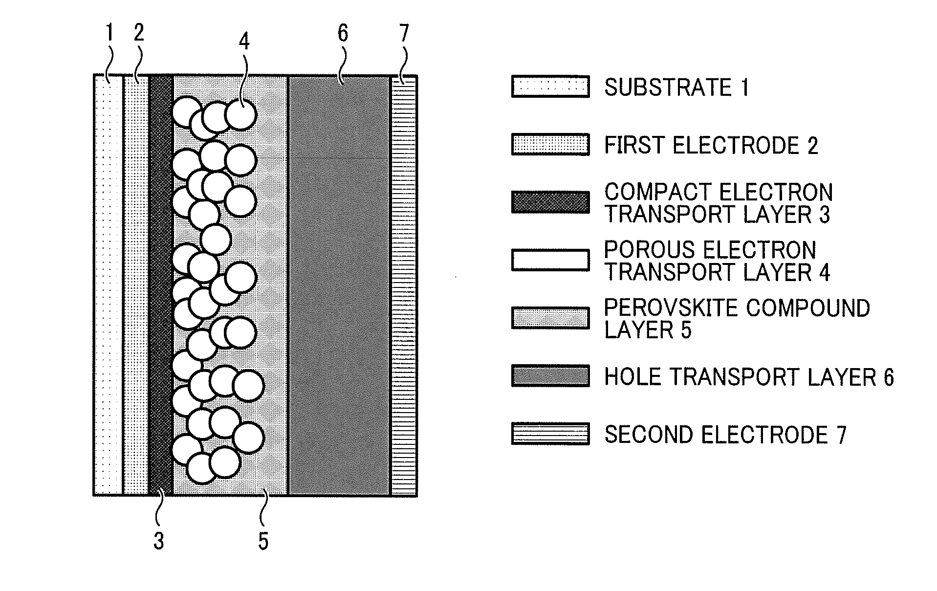
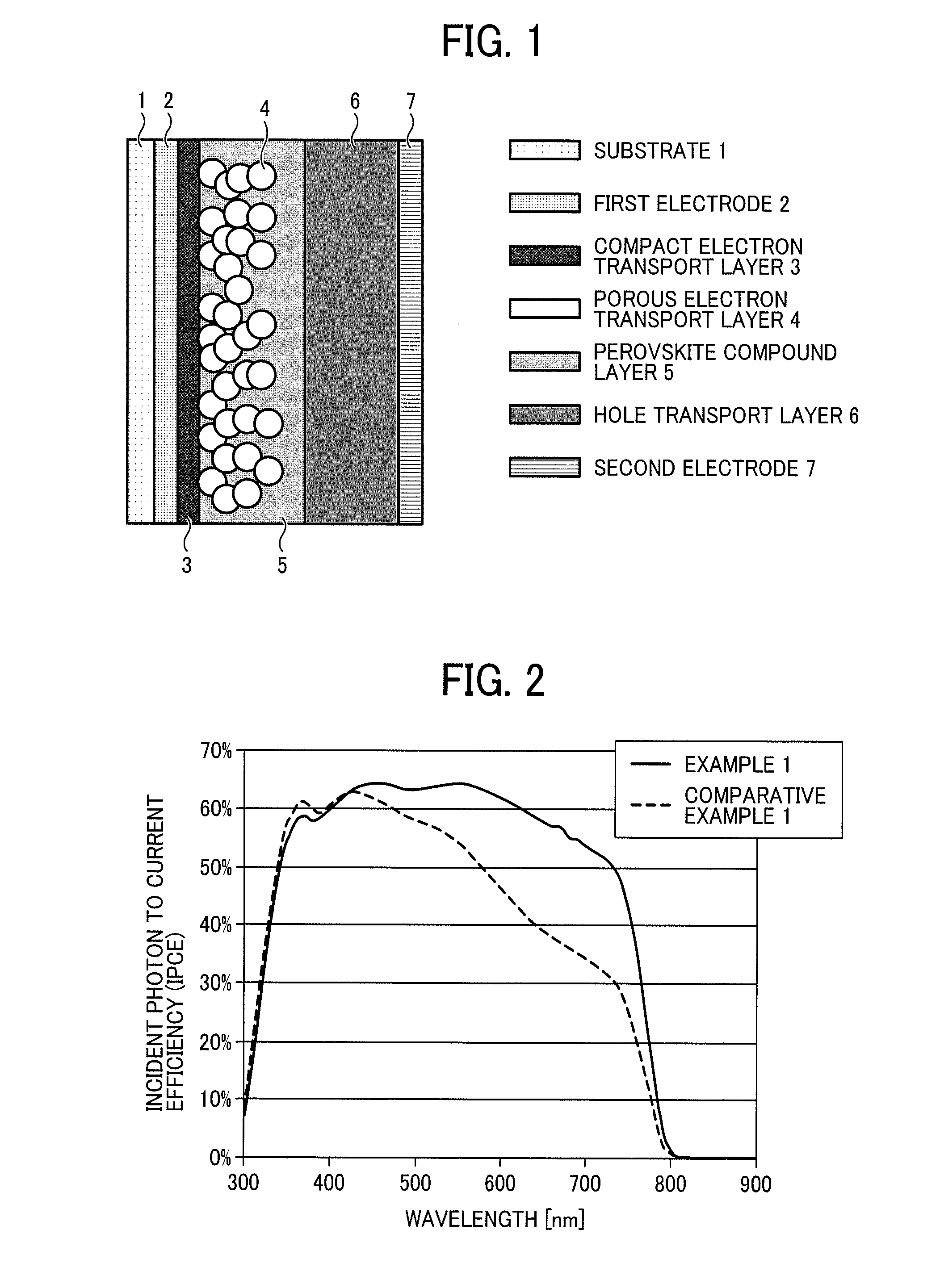
Image

Examples
example 1
Manufacture of a Titanium Oxide Semiconductor Electrode
[0112]A solution of a mixture 2 mL of titanium tetra-n-propoxide, 4 mL of acetic acid, 1 mL of ion exchanged water, and 40 mL of 2-propanol is spin coated onto a FTO glass substrate and dried at room temperature. After drying, the coated FTO glass substrate is fired at 450° C. in air for 30 minutes. Accordingly, an electrode is obtained. Employing the above-described solution, spin coating is conducted until a film thickness of 50 nm is obtained on the electrode and is fired at 450° C. in air for 30 minutes. Accordingly, a compact electron transport layer is formed.
[0113]A titanium oxide paste 18NR-T (from Dyesol Ltd.) is spin coated on the above-described compact electron transport layer until a film thickness of 300 nm is obtained. Then, it is subjected to warm-air drying for 3 minutes at 120° C. After warm-air drying, the coated compact electron transport layer is fired at 500° C. in air for 30 minutes. Accordingly, a porous ...
example 2
[0120]A solar cell element of example 2 was obtained with the above-described procedure of example 1 except for replacing the solution of 1.0 ml of N,N-dimethylformamide including dissolved 0.438 g of lead (II) iodide and 0.025 g of antimony (III) iodide with a solution of 1.0 ml of N,N-dimethylformamide including dissolved 0.415 g of lead (II) iodide and 0.050 g of antimony (III) iodide. The above-described evaluation of example 1 was repeated for the solar cell element of example 2.
[0121]The results show good properties. More specifically, the results show an open circuit voltage of 0.90V, a short circuit current density of 15.9 mA / cm2, form factor of 0.62, and a conversion efficiency of 8.87%.
example 3
[0122]A solar cell element of example 3 was obtained with the above-described procedure of example 1 except for replacing the solution of 1.0 ml of N,N-dimethylformamide including dissolved 0.438 g of lead (II) iodide and 0.025 g of antimony (III) iodide with a solution of 1.0 ml of N,N-dimethylformamide including dissolved 0.392 g of lead (II) iodide and 0.075 g of antimony (III) iodide. The above-described evaluation of example 1 was repeated for the solar cell element of example 3.
[0123]The results show good properties. More specifically, the results show an open circuit voltage of 0.88V, a short circuit current density of 14.9 mA / cm2, form factor of 0.66, and a conversion efficiency of 7.84%.
PUM
 Abstract
Description
Claims
Application Information