
Abrasive article and method for making the same

a technology of abrasive articles and abrasive particles, which is applied in the direction of abrasive equipment, pigmentation treatment, other chemical processes, etc., can solve the problems of hammering the performance and usable life of abrasive tools, limited cutting ability, and poor abrasive particle retention, so as to reduce the overall amount of abrasive particles needed, reduce the cost of making tools, and increase the service life of expensive abrasive particles

Inactive Publication Date: 2015-10-15
LI YUNDONG
View PDF0 Cites 68 Cited by
  • Summary
  • Abstract
  • Description
  • Claims
  • Application Information

AI Technical Summary

Benefits of technology

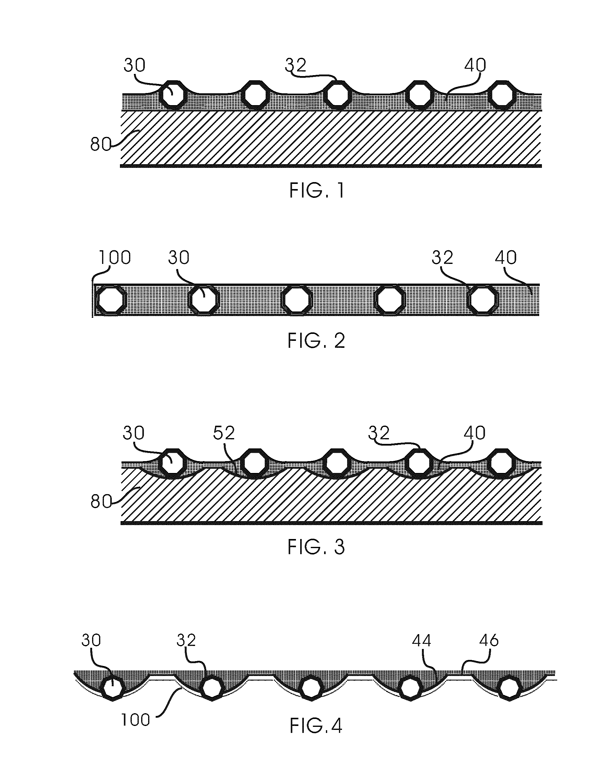
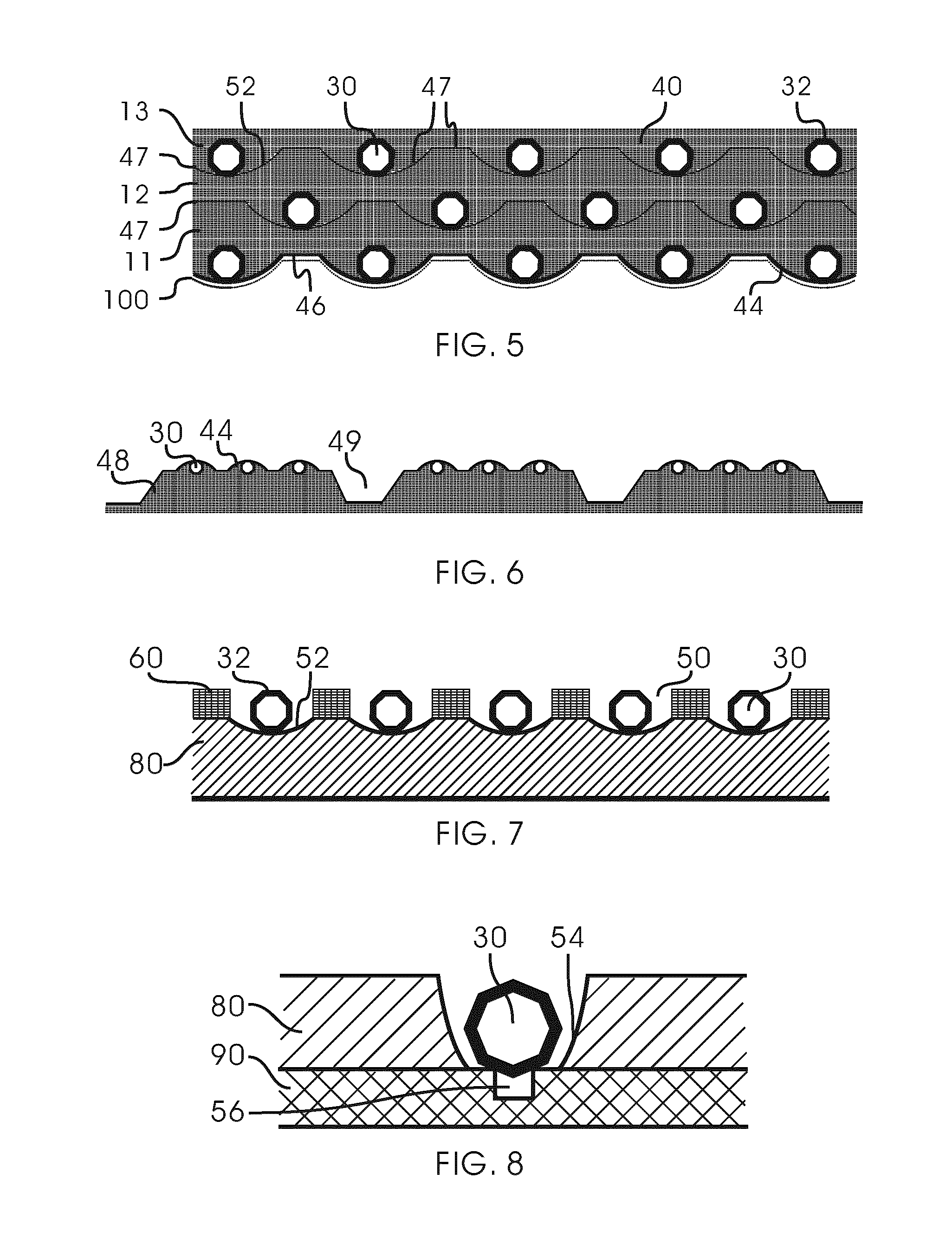
The present invention provides a way to increase the service life of expensive abrasive particles and minimize costs by reducing the amount of abrasive particles needed in a customized particle pattern while maximizing efficiency and performance characteristics by using previously coated abrasive grains that enable chemical bonding and precise arrangement of grains in abrasive products. This results in a non-uniform pattern that compensates for uneven wear and includes reinforced areas with higher concentration of grains, more abrasive type of grains, higher quality of grains, harder matrix, smaller size of grains, lower protrusion height of grains, less apex-oriented and more face-oriented grains towards the workpiece, or combinations thereof.

Problems solved by technology

Despite their practical use in industries, a number of issues continue to hamper the performance and usable life of abrasive tools.
For example, grain retention remains problematic.
As a result, grains are often pulled out prematurely, or the height of protrusion of grains is compromised, e.g. less than ⅓ to ½ of the average diameter of the particles, resulting in a limited cutting ability.
Another limitation associated with the conventional abrasive tools is that the grains are not arranged to maximize efficiency for cutting, drilling, grinding, polishing, etc.
Though abrasive tools with abrasive chemically bonded and regularly arranged have been successfully developed by brazing (WO2012 / 162430, WO2010 / 141464, U.S. Pat. No. 6,416,560, U.S. Pat. No. 6,679,243 and U.S. Pat. No. 8,104,464), the bonding strength between grains and brazed material is limited because of thermal residual stress induced during cooling period from high brazing temperature; degradation of grain surface (e.g. graphitization of diamond) because of high brazing temperature; and compromises made when selecting material, temperature and equipment for the brazing process.
In addition, it is difficult for brazing method to achieve accurate grain positioning pattern and protruding height because of further movement of placed particles following melting of the brazing material.
It is also difficult or even impossible for the brazing technique to obtain products with thin blade, high precision and complex shape by means of lower cost.
But no chemical bonding is reported in these tools probably due to the use of naked abrasive grains which have unique surface characteristics (e.g. bad wettability and non-platability of diamond).
In addition, spaces are left among the abrasive grains and pores are fully uniformly dispersed in the electrodeposited abrasive layer (U.S. Pat. No. 4,547,998), which markedly decreases the abrasive retention.
But, the abrasive retention is compromised.
Further, a vitreous bond tool wherein the grains are arranged in a predetermined pattern is reported in U.S. Pat. No. 6,755,720, but no chemical bonding is achieved.

Method used


Image

  • Abrasive article and method for making the same
  • Abrasive article and method for making the same
  • Abrasive article and method for making the same

Examples


example 1

[0109]A stainless steel disc (120D-0.65T) that is about 120 mm in diameter and about 0.65 mm in thickness is partially covered by an electrically non-conductive template having a plurality of apertures distributed in a lattice pattern. The template covers a generally circular area on a central portion of the disc of about 100 mm in diameter, leaving a width of about 10 mm around the perimeter of the disc. The perimeter area is covered by an insulating material to prevent deposition. The aperture separation measuring from the approximate center points of adjacent apertures is about 800 microns with each aperture about 400 microns in diameter. Nickel coated diamond particles with an average size of 300 microns are then dispersed into the apertures so that each aperture accommodates only a single grain. The excess diamond grains are discarded by brushing, titling, vibrating, shaking, etc. The located diamond grains are bonded to the steel substrate by an electroplating process. A 99.99...

example 2

[0110]The process of Example 1 is followed, except the diamond grains used in the present example are naked (with no metallic coating) and magnetically sensitive as a result of containing inclusions of catalysts such as nickel, cobalt, iron, manganese, or like. These grains are normally excluded in fabrication of electroplated diamond tools because they lead to the formation of nodules around diamond grains, over-plating of the grains, and pores in plated material between grains. Individual placement of the grains in the present invention successfully prevents the formation of such pores which are detrimental to the abrasive retention.

example 3

[0111]A substrate metal having a shape and a dimension of 240D-20T is prepared from stainless steel (SUS304) by working using a lathe. Then, the substrate surface is covered by an electrically non-conductive template, and the other part is masked with an insulation tape. The template has apertures in grid pattern with aperture diameter of 200 microns and aperture separation of 400 microns. The substrate is then treated for degreasing with an alkali and dipped into a pretreatment fluid containing 240 g / liter of nickel chloride and 100 g / liter of hydrochloric acid. The dipped substrate is set to an anode and electrolytically etched under a current density of 10 A / dm.sup.2 at an ordinary temperature for 2 minutes. Then, the substrate is set to a cathode, and strike plating is conducted for 3 minutes. The treated substrate is plated in a plating bath of nickel sulfamate under a current density of 1 A / dm.sup.2 for 15 minutes to form a thin plating underlayer. The purpose of the early pla...


PUM

PropertyMeasurementUnit
Grain sizeaaaaaaaaaa
Forceaaaaaaaaaa
Structureaaaaaaaaaa

Abstract

An abrasive article comprising a plurality of abrasive grains that are precisely arranged in accordance with a predetermined pattern and are chemically bonded with a matrix material, and a method for the making thereof are disclosed. A coating layer on each of the abrasive grains functions as a bridge to form chemical bonding between the abrasive grains and the matrix material. In addition to a plated material, the matrix material can include a braze, a solder, a sintered material, an infiltrant, an organic material, and a vitrified material. The method for making the abrasive article comprises the steps of: coating abrasive grains with a coating layer that chemically bonds to each of the abrasive grains; arranging the coated abrasive grains in accordance with a predetermined pattern; and chemically bonding the coated abrasive grains with a matrix material.

Description

TECHNICAL FIELD[0001]The present invention relates generally to abrasive articles and processes for producing the same. More particularly, the present invention relates to an abrasive tool which comprises abrasive grains chemically bonded and precisely arranged in accordance with a predetermined pattern. Accordingly, the present invention involves the fields of materials science, mechanical engineering, and physics.BACKGROUND ART[0002]Diamond, the hardest abrasive currently known, is widely used on saws, drills, and other devices to cut, form, or polish materials such as aluminum, copper, carbide alloy, stone, concrete, asphalt, glass, ceramics, gem stone, semiconductor materials, rubber and resin, while the other super abrasive tool, cubic boron nitride (CBN) tool, is suitable to process steels including common steels and various tough alloy steels. According to their manufacturing methods or bond types, abrasive tools can be categorized into several types, such as metal-bonded (i....

Claims


Application Information

Patent Timeline
IPC IPC(8): B24D3/06B24D18/00
CPCB24D3/06B24D18/0018B24D18/0072
Inventor LI, YUNDONG
Owner LI YUNDONG
Learn More