Method and Device for Obtaining Purified Water

a technology of purification water and purification device, which is applied in the field of methods and, can solve the problems of high pressure pump and difficulty in obtaining water below boiling point, and achieve the effects of low impurity concentration, high durability, and stable manufacturing

Inactive Publication Date: 2015-10-22
ASAHI KASEI CHEM CORP
View PDF10 Cites 5 Cited by
  • Summary
  • Abstract
  • Description
  • Claims
  • Application Information

AI Technical Summary

Benefits of technology

[0035]According to the method of the present invention, the purified water can be manufactured stably for a long period of time, and the purified water of low impurity concentration can be manufactured. In addition, according to the membrane module and the purified water manufacturing device of the present invention, the membrane module for manufacturing the purified water and the purified water manufacturing device that are high in durability, and are capable of stably manufacturing the purified water of the low impurity concentration and being easily operated can be provided.

Problems solved by technology

Although this method is widely used, the problem is in the fact that a high pressure pump is needed and devices in many stages are needed in order to sufficiently lower a salt concentration in the purified water are problems.
The distillation method has disadvantages in that it is difficult to obtain the water below a boiling point, a device is large-sized, and the like.

Method used


Image

  • Method and Device for Obtaining Purified Water
  • Method and Device for Obtaining Purified Water
  • Method and Device for Obtaining Purified Water

Examples


example 1

[0131]The gas-permeable membrane was manufactured by coating Teflon® AF-1600 (made by DuPont) to a polyethersulfone hollow fiber microporous membrane whose outer diameter is 1 mm and inner diameter is 0.7 mm. The oxygen permeation rate was 1200 GPU, it was the oxygen permeation rate / nitrogen permeation rate ratio=23, and the vapor permeation rate was 5400 GPU. The water absorption rate of the AF-1600 membrane was 0.01% or lower, and a contact angle with the water was 104°. The water absorption rate was measured under the condition that the sample was immersed in the water at 23° C. for 24 hours according to ASTM570. The contact angle with the water was measured using a contact angle measuring device (made by Kyowa Interface Science, CA-X150 type contact angle meter) after putting a droplet of deionized water on a surface of the sample and leaving it for one minute at 23° C. The hollow fibers were bundled to manufacture four pieces of membrane module 11 of 10 m2, and the membrane mod...

example 2

[0135]The gas-permeable membrane was manufactured by coating Teflon® AF-1600 to a polyolefin-based microporous membrane. Oxygen permeability was 1300 GPU, it was the oxygen permeation rate / nitrogen permeation rate ratio=2.3, and the vapor permeation rate was 5900 GPU. The water absorption rate of the AF-1600 membrane was 0.01% or lower, and a contact angle with the water was 104°. The water absorption rate was measured under the conditions that the sample was immersed in the water at 23° C. for 24 hours according to ASTM570. The contact angle with the water was measured using the contact angle measuring device (made by Kyowa Interface Science, CA-X150 type contact angle meter) after putting the droplet of the deionized water on the surface of the sample and leaving it for one minute at 23° C. A plain-woven net of 500 denier and 10 mesh was turned to the spacer, the gas-permeable membrane was held by the spacer and processed into pleats. Four pieces of the membrane module of 10 m2 we...


PUM

PropertyMeasurementUnit
temperatureaaaaaaaaaa
water contact angleaaaaaaaaaa

Abstract

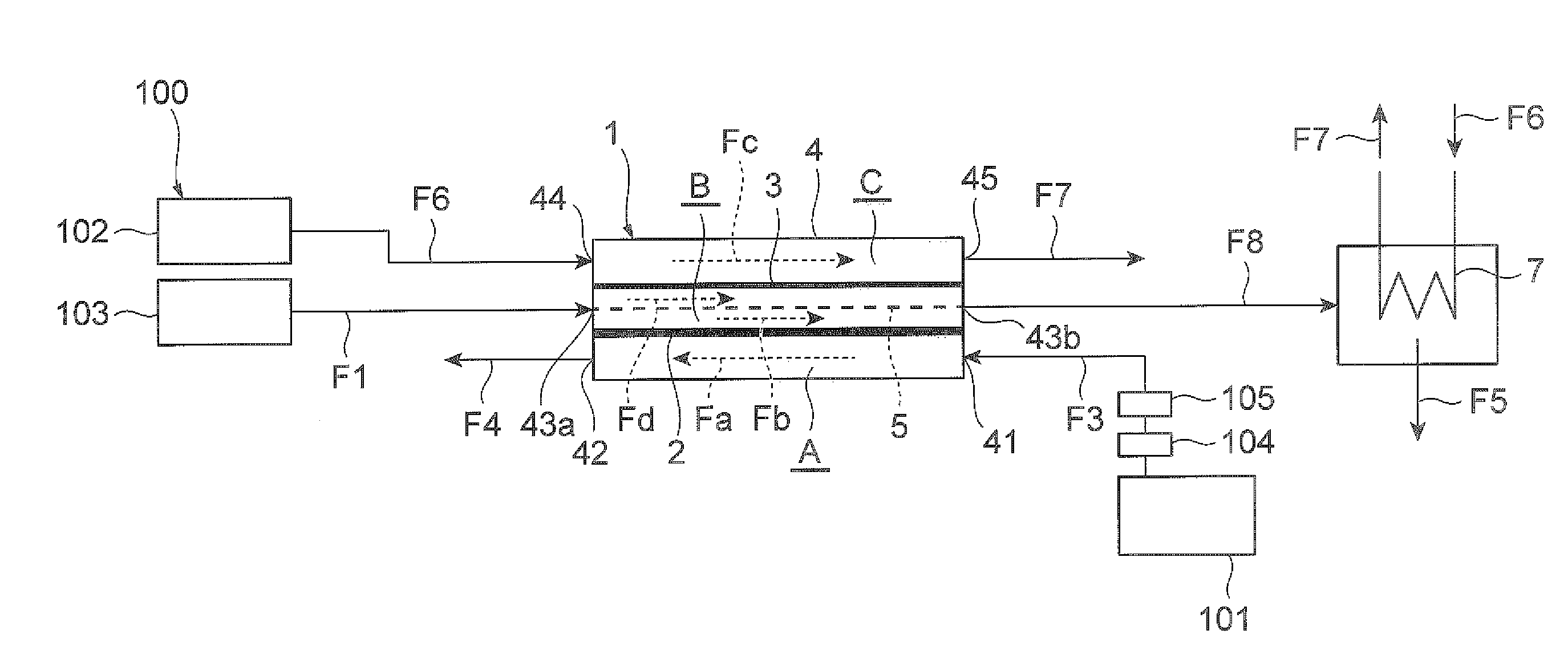
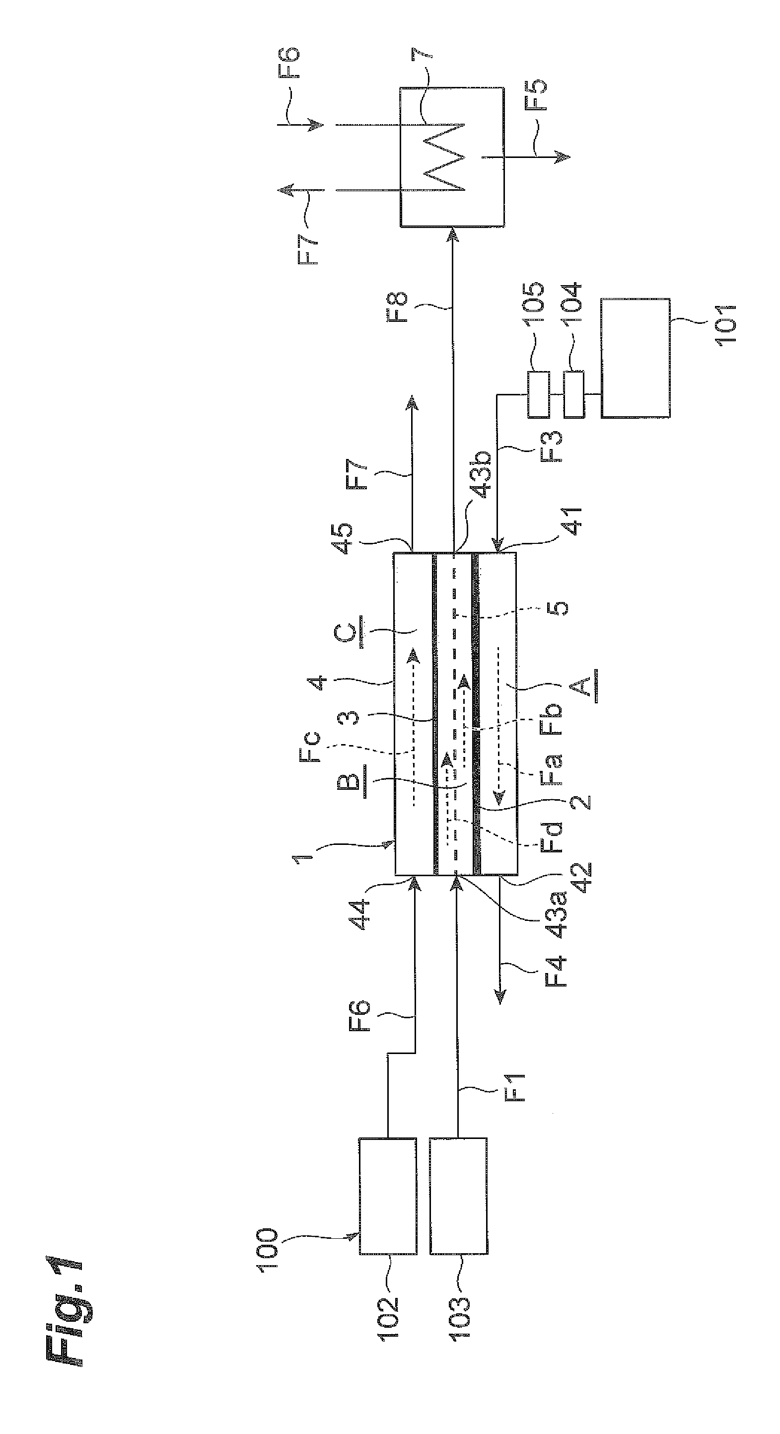
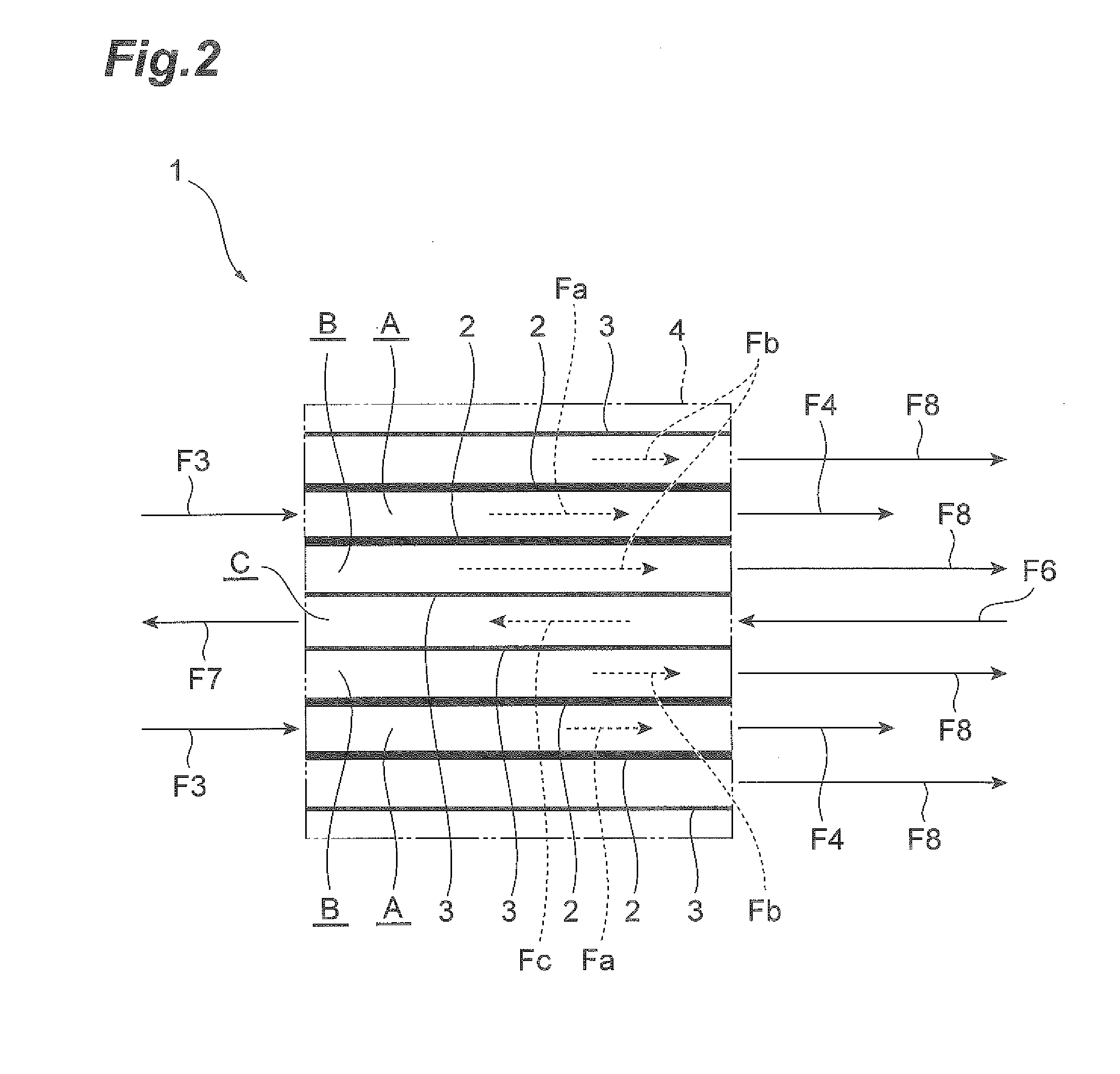
A main object is to provide a method, a membrane module and a purified water manufacturing device that demonstrate a performance of manufacturing water stably for a long period of time and lower a salt concentration in purified water. In the method, raw water is made to flow along one surface of a gas-permeable membrane, vapor permeated through the gas-permeable membrane is condensed, and the purified water is obtained.

Description

TECHNICAL FIELD [0001]The present invention relates to a method for obtaining water with few impurities (called purified water, hereinafter) from water that contains impurities such as seawater or wastewater (may contain electrolytes such as organic salt / inorganic salt, other dissolved components, dispersions or microorganisms in particular) (called raw water, hereinafter), a membrane module, and a purified water manufacturing device. More in detail, the present invention relates to a method for subjecting raw water to membrane distillation using a gas-permeable membrane and manufacturing water, a membrane module, and a purified water manufacturing device.BACKGROUND ART [0002]Conventionally, as a method for obtaining the purified water from the raw water, a reverse osmosis membrane method, a distillation method and a membrane distillation method are known.[0003]The reverse osmosis membrane method is a method for obtaining the purified water by treating salt water by a reverse osmosi...

Claims


Application Information

Patent Timeline
Patent Type & Authority Applications(United States)
IPC IPC(8): C02F1/44B01D61/36B01D63/14
CPCC02F1/447B01D63/14B01D61/364C02F2209/40C02F2103/08B01D2311/10C02F2209/02C02F2101/10B01D2311/106B01D2313/221Y02W10/37B01D61/36C02F1/44C02F2201/002C02F2301/02Y02W10/00
Inventor SHIMIZU, ATSUSHIOHNO, HIROKAZUNIIHAMA, TOMOHIRO
Owner ASAHI KASEI CHEM CORP
Why Eureka
Try Eureka