Gas barrier film

Active Publication Date: 2015-11-26
TORAY IND INC
View PDF6 Cites 4 Cited by
  • Summary
  • Abstract
  • Description
  • Claims
  • Application Information

AI Technical Summary

Benefits of technology

The present invention provides a gas barrier film that has excellent gas barrier properties and high flex resistance without increasing film thickness or forming a multi-layered structure. The gas barrier film has high gas barrier properties against water vapor and high flex resistance.

Problems solved by technology

However, the method of forming a layer with gas barrier properties containing silicon oxide as primary component by the plasma CVD technique as proposed in Patent document 1 cannot always ensure stable gas barrier properties because the film properties of the resulting gas barrier layer will be largely dependent on the type of base material used.
A solution to the stabilization of gas barrier properties is thickening of the film, but this will lead to problems such as a decrease in flex resistance and an increase in production cost.
In the case of the method of using a polysilazane layer to form a layer with gas barrier properties as proposed in Patent documents 5 and 6, furthermore, the layer production conditions can have large influence and a plurality of polysilazane layers have to be stacked to ensure stable formation of gas barrier film having required gas barrier properties, possibly causing problems such as deterioration in flex resistance and increase in production cost.

Method used


Image

  • Gas barrier film
  • Gas barrier film
  • Gas barrier film

Examples


example 1

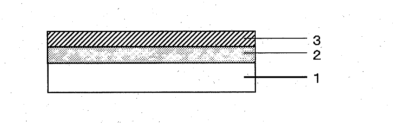
[0166]Polyethylene terephthalate film (Lumirror (registered trademark) U48, manufactured by Toray Industries, Inc.) with a thickness of 50 μm was used as polymer base, and an inorganic layer [A1] with a thickness of 180 nm was formed on one side of this polymer base. In regard to the composition of the inorganic layer [A1], the atom concentration was 27.5 atom % for the Zn atom, 13.1 atom % for the Si atom, 2.3 atom % for the Al atom, and 57.1 atom % for the O atom. A 100 mm length×100 mm width test piece was cut out of the film provided with the inorganic layer [A1] and the center plane average roughness SRa of the inorganic layer [A1] was evaluated. Results are given in Table 1.

[0167]Subsequently, 100 parts by mass of a coating material containing perhydropolysilazane (primary component) and a palladium based catalyst (NL120-20, manufactured by AZ Electronic Materials plc, solid content 20 parts by mass) was diluted with 300 parts by mass of dibutyl ether to prepare a coating liqu...

example 2

[0174]Polyethylene terephthalate film (Lumirror (registered trademark) U48, manufactured by Toray Industries, Inc.) with a thickness of 50 μm was used as polymer base. Then, 150 parts by mass of the polyurethane compound, 20 parts by mass of dipentaerythritol hexaacrylate (Light Acrylate DPE-6A (trade name), manufactured by Kyoeisha Chemical Co., Ltd.), 5 parts by mass of 1-hydroxy-cyclohexyl phenyl-ketone (Irgacure 184 (trade name), manufactured by BASF Japan), 3 parts by mass of 3-methacryloxypropyl methyl diethoxy silane (KBM-503 (trade name), manufactured by Shin-Etsu Silicones), 170 parts by mass of ethyl acetate, 350 parts by mass of toluene, and 170 parts by mass of cyclohexanone were mixed to prepare a coating liquid, which is referred to as coating liquid 2, to be used for forming a undercoat layer [C]. Subsequently, coating liquid 2 was spread on a polymer base with a Micro Gravure Coater (gravure line number 15OUR, gravure rotation ratio 100%) and dried at 100° C. for 1 m...

example 3

[0188]Except for using an amorphous cyclic polyolefin film (Zeonor Film ZF14, manufactured by Zeon Corporation) with a thickness of 100 μm as the polymer base, the same procedure as in Example 1 was carried out to produce a gas barrier film.


PUM

PropertyMeasurementUnit
Phaseaaaaaaaaaa
Mole fractionaaaaaaaaaa

Abstract

The gas barrier film includes a polymer base having an inorganic layer [A] and a silicon compound layer [B] stacked in this order at least on one side of the polymer base, the inorganic layer [A] containing a zinc compound and silicon oxide, the silicon compound layer [B] containing silicon oxynitride, and the inorganic layer [A] and the silicon compound layer [B] being in contact with each other.

Description

CROSS REFERENCE TO RELATED APPLICATION[0001]This is the U.S. National Phase application of PCT / JP2013 / 084626, filed Dec. 25, 2013, which claims priority to Japanese Patent Application No. 2013-003089, filed Jan. 11, 2013, and Japanese Patent Application No. 2013-236569, filed Nov. 15, 2013, the disclosures of each of these application being incorporated herein by reference in their entireties for all purposes.FIELD OF THE INVENTION[0002]The present invention relates to gas barrier film to be used for packaging of foodstuffs and pharmaceuticals, electronic devices such as solar battery, electronic paper, and organic electroluminescent (EL) displays, and other materials that are required to have high gas barrier properties.BACKGROUND OF THE INVENTION[0003]Gas barrier films that contain a polymer base having an layer of an inorganic substance (or inorganic oxide) such as aluminum oxide, silicon oxide, and magnesium oxide deposited on a surface thereof by a physical vapor deposition (PV...

Claims


Application Information

Patent Timeline
IPC IPC(8): C09D1/00C23C14/08C08J7/046C08J7/048
CPCC09D1/00Y10T428/31598C23C14/08C23C14/086C08J2365/00C08J2367/02C08J2475/04C08J2483/16C08J7/0423C08J7/048C08J7/046H10K50/841
Inventor MORI, KENTAROUEBAYASHI, HIROYUKI
Owner TORAY IND INC
Why Eureka
Try Eureka