Structural repair having optical witness and method of monitoring repair performance

a structural repair and optical witness technology, applied in the field of aircraft, can solve the problems of local strain within the patch and/or surrounding structure to change, and achieve the effect of quick and easy monitoring of the performance of the repair

Active Publication Date: 2015-11-26
THE BOEING CO
View PDF7 Cites 16 Cited by
  • Summary
  • Abstract
  • Description
  • Claims
  • Application Information

AI Technical Summary

Benefits of technology

[0007]An optical witness or ‘tell-tale’ feature is incorporated into a structural repair that allows the performance of the repair to be quickly and easy monitored. Changes in the repair, including early partial failure or degradation of a repair can be visually identified so the repair can be more frequently monitored, repaired, or replaced as needed. In one embodiment, stress sensitive fluorescent dyes are incorporated into the pigment of an appliqué placed over the repair area or in the resin of the surface or overlay ply of the repair. The optical behavior of the fluorescent dye changes as a function of a stress in the repair.
[0009]The cost of incorporating a witness dye into an appliqué or in the resin of a surface ply is relatively low. The inspection / monitoring method does not require a highly trained NDE technician or expensive NDE equipment. The inspection method and optical witness may reduce or eliminate the need for complicated and expensive structural health monitoring (SHM) equipment or on-board sensors. The mechanochromatic dye may be used at a relatively low level in order to avoid significantly increasing the weight of a resin in an overlay ply. In some embodiments, when the dye is incorporated into an appliqué, the appliqué may also function as lightning strike protection, and may be selected to provide a color that matches the structure around it.

Problems solved by technology

When the bond in a repair begins to degrade, the adhesive disbonds from the repaired structure causing the local strain within the patch and / or surrounding structure to change.

Method used


Image

  • Structural repair having optical witness and method of monitoring repair performance
  • Structural repair having optical witness and method of monitoring repair performance
  • Structural repair having optical witness and method of monitoring repair performance

Examples


example 1

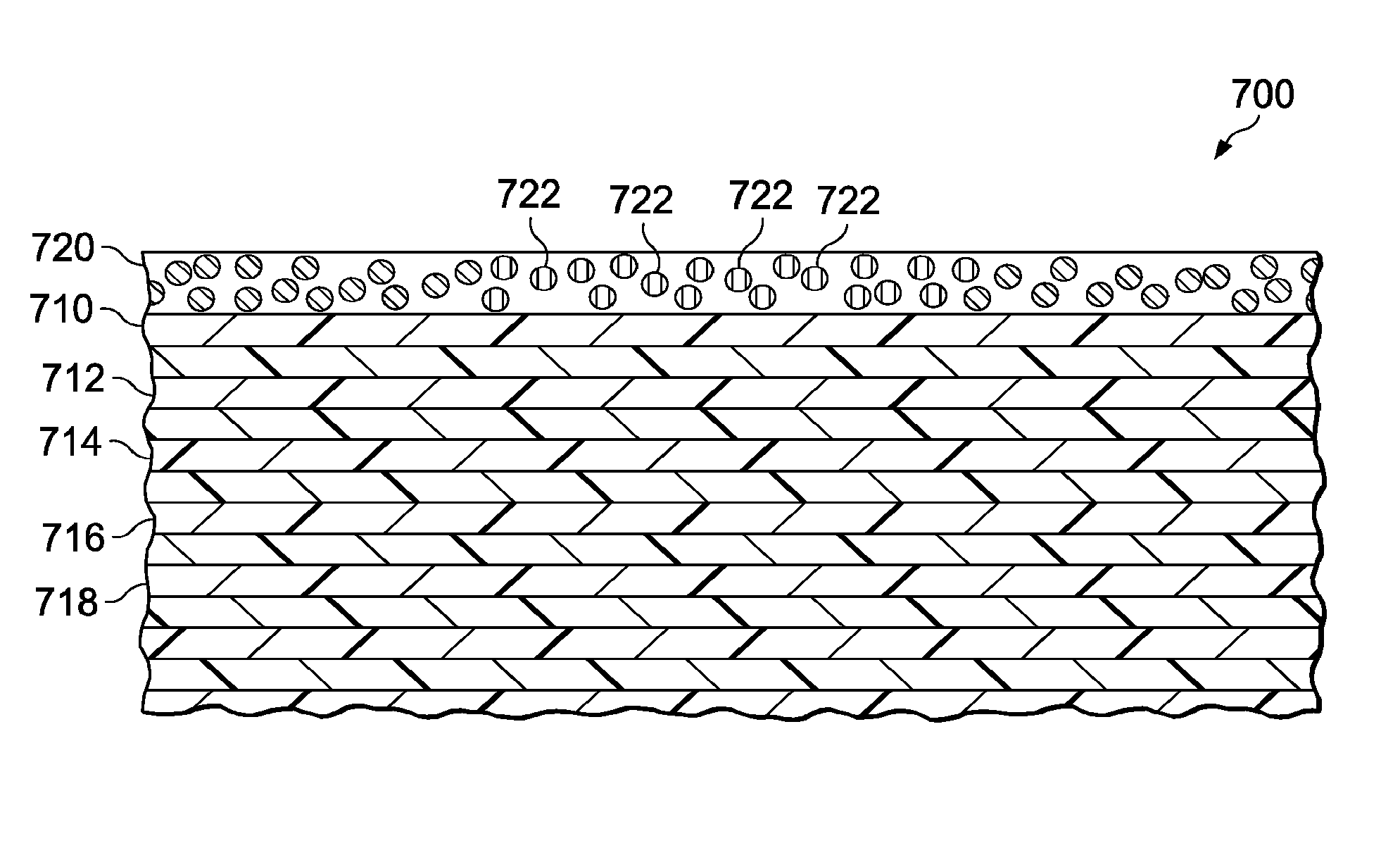
[0078]A coating system of an epoxy based primer and a polyurethane (PU) topcoat was prepared on a 0.1 millimeter polyethylene terephthalate substrate. DesoPrime 7501, available from PPG Aerospace, Pittsburgh, Pa., was selected as the epoxy-based primer. DesoPrime 7501 comprises a curing agent and epoxy monomers. The curing agent is a mixture of paint solids, n-butyl alcohol, and aliphatic amines. The epoxy monomer comprises bisphenyl A and Epichlorohydrin-based resin in an acetone solvent.

[0079]A modified stilbene-type fluorescent dye was synthesized and prepared as a dry powder. The modified stilbene-type molecules were prepared having tert-butyl dimethyl silane end groups. The selected end groups were selected to be non-reactive with other components of the epoxy-based primer. The modified stilbene-type fluorescent dye was added to the epoxy monomer in an amount of 8.2*10̂-4 mol / L of epoxy monomer solution, which was measured using a conventional fluorescence probe (probe 6 shown ...

example 2

[0083]A coating system of an epoxy based primer and a polyurethane topcoat was prepared on a 0.1 millimeter polyethylene terephthalate substrate. DESOPRIME 7501, available from PPG Aerospace, Pittsburgh, Pa., was selected as the epoxy-based primer. DESOPRIME 7501 comprises a curing agent and epoxy monomers. The curing agent is a mixture of paint solids, n-butyl alcohol, and aliphatic amines. The epoxy monomer comprises bisphenyl A and Epichlorohydrin-based resin in an acetone solvent.

[0084]A modified stilbene-type fluorescent dye was synthesized and prepared as a dry powder. The modified stilbene-type molecules were prepared having hydroxyl end groups. The selected end groups were selected to be reactive with other components of the epoxy-based primer, and become part of the thermoset network formed as the epoxy cures. The modified stilbene-type fluorescent dye was added to the epoxy monomer in an amount of 1.28*10̂-3 mol / L of epoxy monomer solution, which was measured using a conve...

example 3

[0090]A coating system of an epoxy based primer and a polyurethane topcoat was prepared on a 0.1 millimeter polyethylene terephthalate substrate. DESOPRIME 7501, available from PPG Aerospace, Pittsburgh, Pa., was selected as the epoxy-based primer. DESOPRIME 7501 comprises a curing agent and epoxy monomers. The curing agent is a mixture of paint solids, n-butyl alcohol, and aliphatic amines. The epoxy monomer comprises bisphenyl A and Epichlorohydrin-based resin in an acetone solvent.

[0091]The epoxy-based primer was prepared in a 1:1 mix ratio, by volume, of curing agent to epoxy monomers. The epoxy-based primer was then applied to the polyethylene terephthalate substrate at a thickness of 20-30 micrometers. The epoxy-based primer was then allowed to cure at room temperature over a period of 48 hours.

[0092]DESOTHANE 8800, available from PPG Aerospace, Pittsburgh, Pa., was selected as the polyurethane topcoat. DESOTHANE 8800 comprises a base component, and activator component, and a ...


PUM

PropertyMeasurementUnit
thicknessaaaaaaaaaa
thicknessaaaaaaaaaa
span lengthaaaaaaaaaa

Abstract

A structural repair includes a tell-tale optical witness that allows the health of the repair to be visually monitored. The optical witness includes a stress sensitive fluorescent dye that shows changes in local strain / stress patterns when the repair is subjected to electromagnetic energy of a particular wavelength. The dyes fluoresce more or less strongly as a function of the local stress / strain.

Description

[0001]This application is a divisional application of U.S. patent application Ser. No. 13 / 310,539, filed Dec. 2, 2011 which claims priority from provisional application No. 61 / 482,737.CROSS REFERENCE TO RELATED APPLICATIONS[0002]This application claims the benefit of Provisional U.S. Patent Application No. 61 / 482,737 filed May 5, 2011, which is incorporated by reference herein in its entirety. This application is also related to co-pending U.S. patent application Ser. No. 13 / 310,333, (Attorney Docket 11-0108-US-NP) filed on even date herewith, which is incorporated by reference herein in its entirety.BACKGROUND INFORMATION 1. Field[0003]The present disclosure relates generally to manufacturing and servicing vehicles, especially aircraft. More particularly, the present disclosure relates to a method of repairing or reworking inconsistencies in components of the aircraft that allow the performance of the repair to be monitored using optical inspection techniques.[0004]2. Background[00...

Claims


Application Information

Patent Timeline
Patent Type & Authority Applications(United States)
IPC IPC(8): G01L5/00B32B33/00
CPCG01L5/00B32B33/00Y10T428/28B32B2307/422B32B2556/00B32B2605/18B29C73/10B29C2035/0827G01M5/0091B64F5/40B32B43/00B23P6/00G01B15/06G01B11/16G01L1/24B32B41/00G01K13/00
Inventor GEORGESON, GARY E.GRIESS, KENNETH HARLANKELLER, RUSSELL LEEWESTERMAN, EVERETT A.
Owner THE BOEING CO
Why Eureka
Try Eureka