Catalytic converter

a catalytic converter and catalyst technology, applied in the direction of physical/chemical process catalysts, metal/metal-oxide/metal-hydroxide catalysts, separation processes, etc., can solve the problems of affecting the efficiency of the catalyst layer, the gas diffusibility to a deep portion of the catalyst layer deteriorates, and the catalyst layer cannot be sufficiently utilized. , to achieve the effect of high cell density, low cell density, and superior thermal shock resistan

Active Publication Date: 2015-12-31
TOYOTA JIDOSHA KK
View PDF3 Cites 4 Cited by
  • Summary
  • Abstract
  • Description
  • Claims
  • Application Information

AI Technical Summary

Benefits of technology

[0020]The catalytic converter according to the present invention preferably has a cordierite honeycomb support having superior thermal shock resistance but may be an electrically heated catalytic converter (EHC: Electrically Heated Converter). In the electrically heated catalytic converter, for example, a pair of electrodes is attached to a honeycomb catalyst, the honeycomb catalyst is heated by causing a current to flow through the electrodes, and the activity of the honeycomb catalyst is improved so as to detoxify the exhaust gas passing therethrough. By applying this electrically heated catalytic converter to an exhaust system for exhaust gas that connects a vehicle engine and a muffler to each

Problems solved by technology

The engine may emit environmentally harmful materials such as CO, NOx, or unburned HC or VOC.
However, since an exhaust gas flow rate distribution in a center region of a cross-section of the substrate is higher than that in a peripheral region thereof, there is a problem in that the catalyst layers of the entire substrate cannot be sufficiently utilized.
However, when a catalytic converter having different cell den

Method used


Image

  • Catalytic converter
  • Catalytic converter
  • Catalytic converter

Examples


embodiment

[0029](Embodiment of Catalytic Converter)

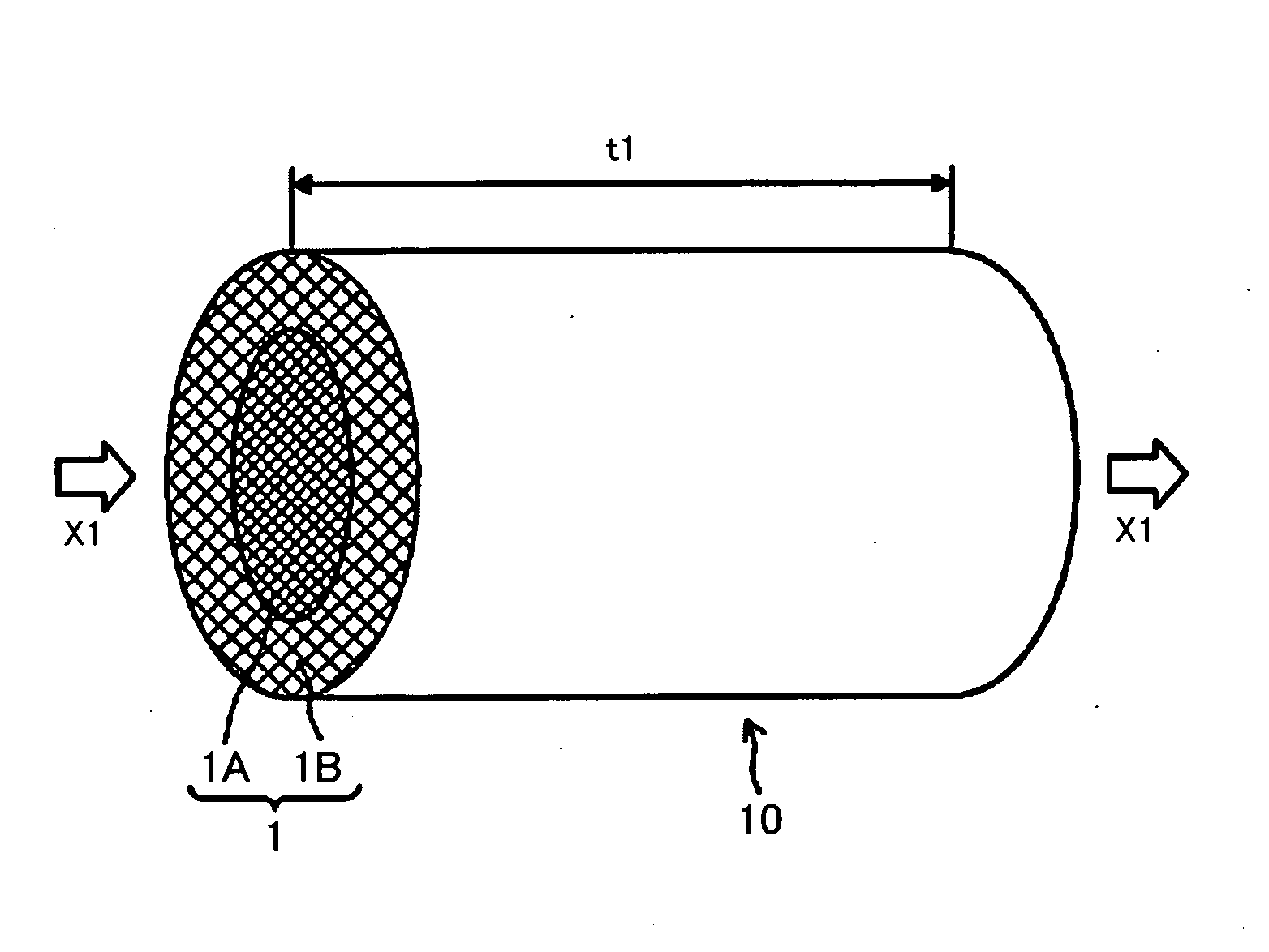
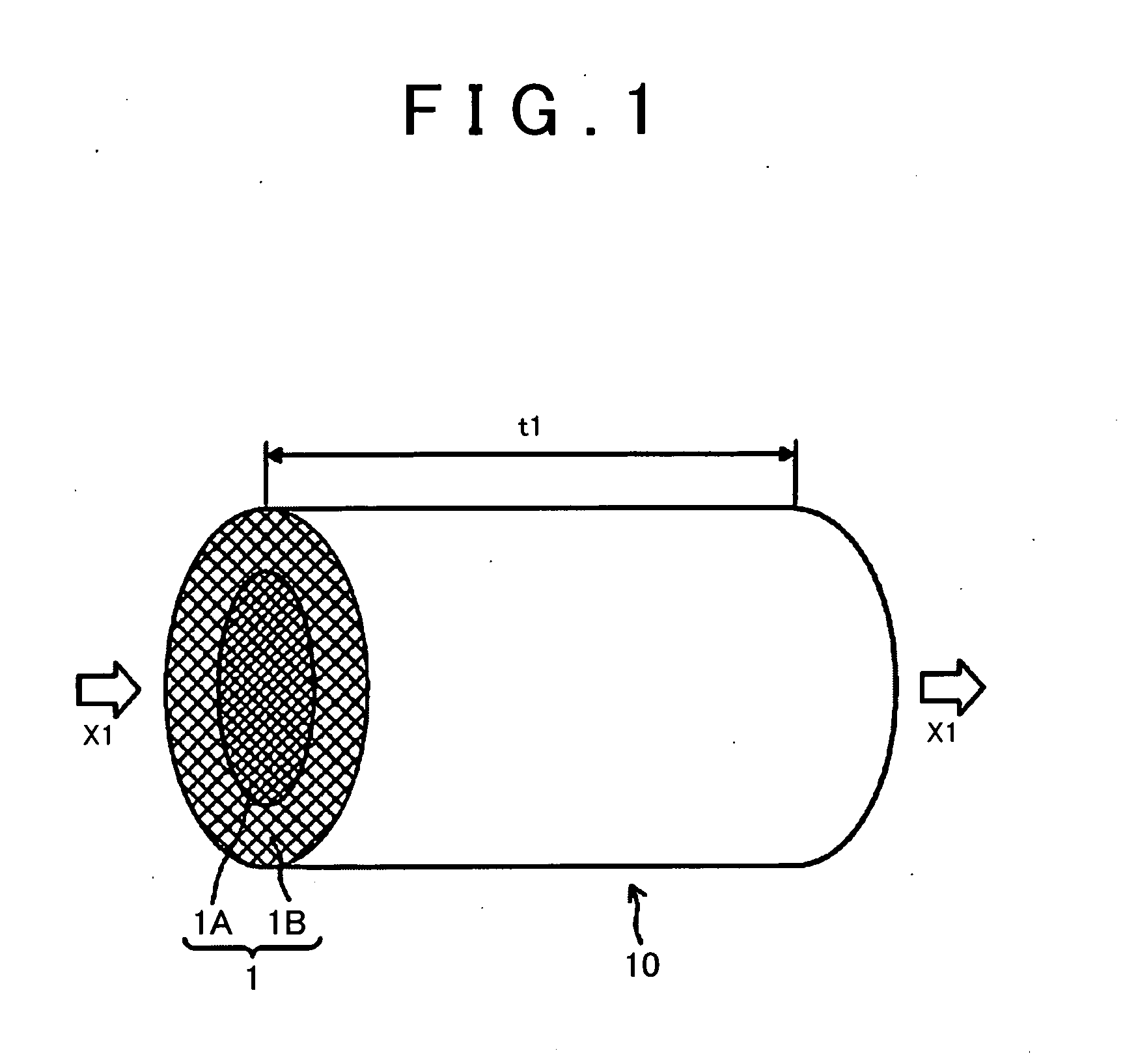
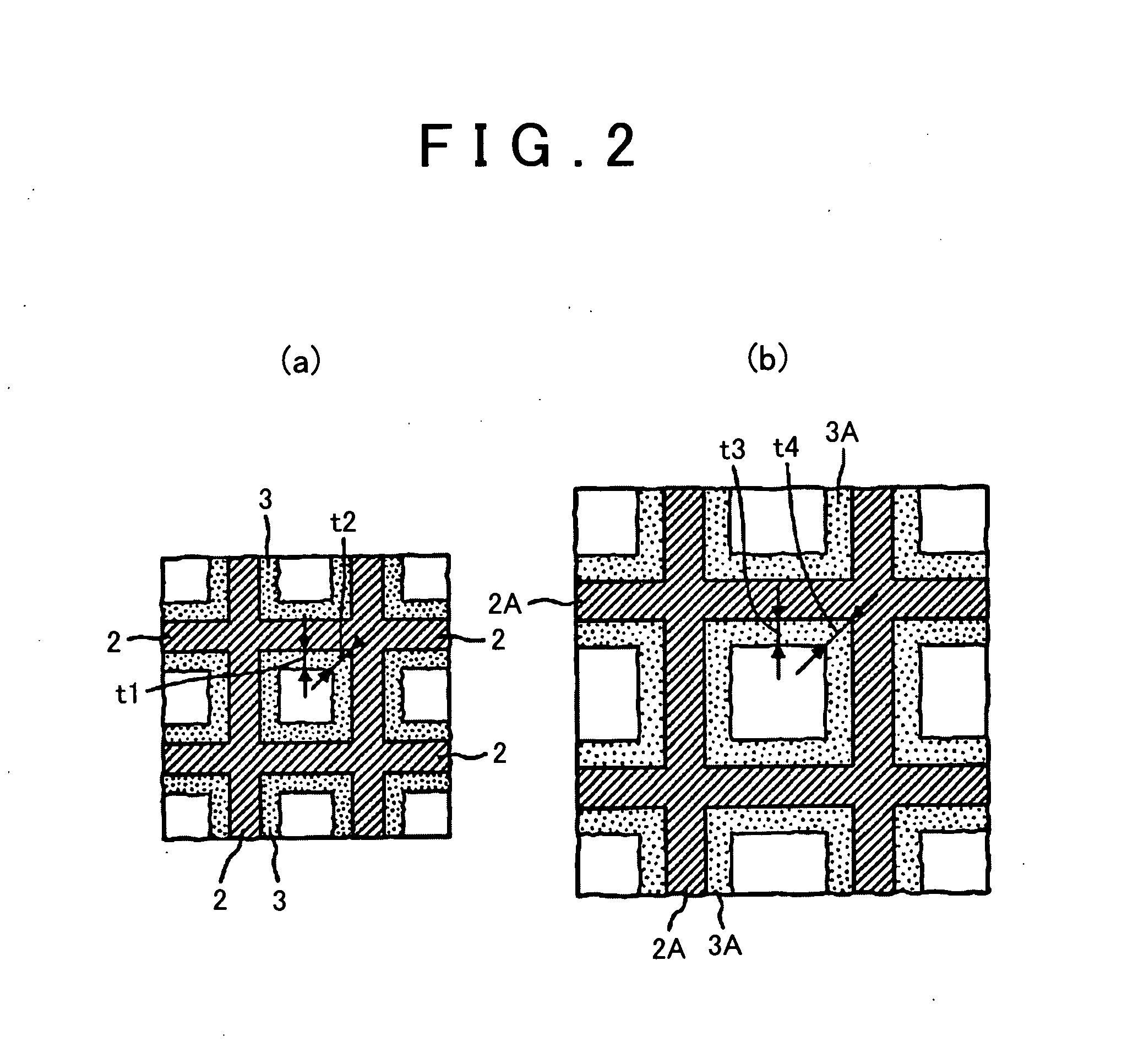
[0030]FIG. 1 is a schematic diagram showing an embodiment of the catalytic converter according to the present invention. FIG. 2(a) is an enlarged view showing cell wall surfaces of a first region (center region) of a substrate, and FIG. 2(b) is an enlarged view showing cell wall surfaces of a second region (peripheral region) of the substrate. In addition, FIG. 3 is a graph showing the exhaust gas flow rate distributions of a substrate having a uniform cell density and the substrate having different cell densities between the center region and the peripheral region.

[0031]Briefly, a catalytic converter 10 shown in FIG. 1 includes: a cylindrical substrate 1 having plural cells; and catalyst layers 3 that are formed on surfaces of cell walls 2 constituting the cells.

[0032]Here, examples of a material of the substrate 1 include a ceramic material such as cordierite or silicon carbide which is formed of a composite oxide of magnesium oxide, alumin...


PUM

PropertyMeasurementUnit
Currentaaaaaaaaaa
Currentaaaaaaaaaa
Digital informationaaaaaaaaaa

Abstract

Provide is a catalytic converter including a substrate which includes regions having different cell densities, in which exhaust gas purification performance is superior in all the regions of the substrate.
A catalytic converter 10 includes catalyst layers in which a noble metal catalyst is supported on a support in surfaces of cell walls 2 of a substrate 1 having a cell structure in a longitudinal direction of the substrate 1 in which gas flows, in which the substrate 1 has a first region 1A having a relatively high cell density and a second region 1B having a relatively low cell density, and a ratio of a thickness of a catalyst layer 3A in the second region 1B to a thickness of a catalyst layer 3 in the first region 1A is in a range of more than 0.95 times and 1.2 times or less.

Description

TECHNICAL FIELD[0001]The present invention relates to a catalytic converter that is accommodated and fixed in a pipe constituting an exhaust system for exhaust gas.BACKGROUND ART[0002]In various industries, various efforts to reduce environmental impacts have been made on a global scale. In particular, in the automobile industry, the development of techniques has progressed for the spread of not only a gasoline engine vehicle having superior fuel efficiency but also a so-called eco-car such as a hybrid vehicle or an electric vehicle and for further improvement in the performance of the vehicles.[0003]Incidentally, in an exhaust system for exhaust gas that connects a vehicle engine and a muffler to each other, a catalytic converter for purifying exhaust gas is generally provided.[0004]The engine may emit environmentally harmful materials such as CO, NOx, or unburned HC or VOC. In order to convert such harmful materials into environmentally acceptable materials, catalyst layers formed...

Claims


Application Information

Patent Timeline
IPC IPC(8): B01J23/46B01J35/04B01J35/00B01D53/94
CPCB01D53/9422B01D53/9413B01D2255/1023B01D2255/1025B01D2255/9032B01D2258/01B01J35/04F01N3/2828F01N2330/06F01N2330/48F01N2330/60B01J35/0006B01J23/40B01J23/464B01J23/63B01J35/023B01D2255/1021
Inventor AOKI, YUKISUZUKI, HIROMASAMATSUBARA, HIROYUKI
Owner TOYOTA JIDOSHA KK
Why Eureka
Try Eureka