Electrospark deposition system for repair of gas turbine

a technology of electrostatic deposition and gas turbine, which is applied in the direction of turbines, soldering devices, auxillary welding devices, etc., can solve the problems of deterioration of fuel nozzles, inability to efficiently repair primary fuel nozzles, and damage to brazed joints, so as to reduce the temperature of shielding gas flow

Inactive Publication Date: 2016-01-14
GENERAL ELECTRIC CO
View PDF5 Cites 3 Cited by
  • Summary
  • Abstract
  • Description
  • Claims
  • Application Information

AI Technical Summary

Benefits of technology

[0008]Another embodiment relates to a system for repairing a metal substrate includes an electrospark device and an electrode removably supported in the electrode holder. The electrospark device applies a coating of a material when placed into contact with the metal substrate. A cooling device to lower the temperature of shielding gas flow below an ambient temperature. A conduit is arranged to direct a flow of the shielding gas at an interface of the electrode and the substrate to cool the area of the substrate receiving the coating.
[0010]Another advantage is that the disclosed ESD process may be operated continuously as long as is necessary to deposit a required coating thickness.
[0011]Still another advantage is the low temperature of the electrode and substrate, as the measured temperature on the electrode is less than 200° F.
[0012]Yet another advantage is the ability to provide a coating thickness of between 2 and 10 mils, which is sufficient to salvage some gas nozzles. Also, a thicker coating of ESD may be deposited if needed.

Problems solved by technology

Over a period of extended use, fuel nozzles may experience deterioration, e.g, around the edges of the nozzle tip.
There is currently no efficient process available to repair a primary fuel nozzle that is manufactured with a brazed joint between the nozzle tip and the body of the nozzle.
Any process to build a metal layer by traditional fusion welding poses a risk that the brazed joint may be damaged by the heat applied by the welding process.
Also, distortion induced by the welding process may not be acceptable for the tolerances required of turbine components such as a primary fuel nozzle.
Laser cladding may be sufficiently low temperature for restoring a nozzle tip to the correct dimensions, but depositing metal on the edge of a nozzle using laser cladding techniques is difficult.
One challenge that the ESD process must overcome is overheating of the electrode and the local substrate, e.g., in a fuel nozzle, where a brazed joint may be compromised by local heating caused by welding or ESD techniques.

Method used


Image

  • Electrospark deposition system for repair of gas turbine
  • Electrospark deposition system for repair of gas turbine
  • Electrospark deposition system for repair of gas turbine

Examples


Embodiment Construction

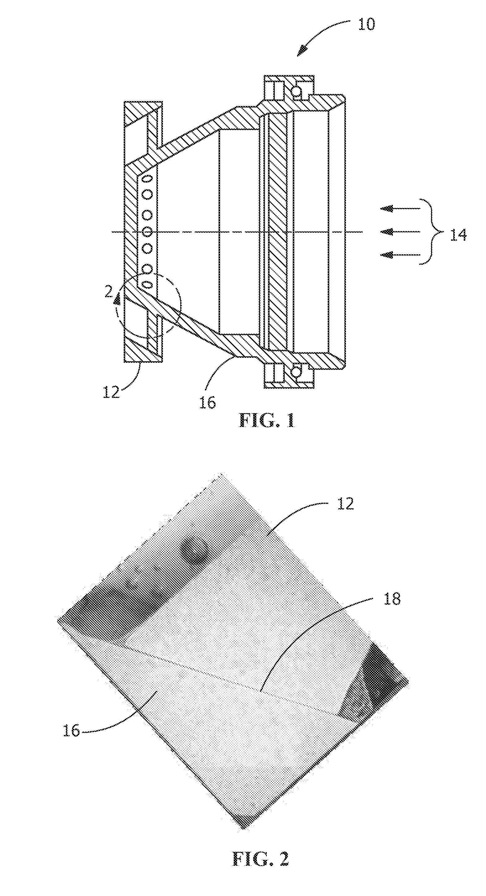
[0019]Referring to FIGS. 1 and 2, a fuel nozzle 10 includes a nozzle tip 12 in fluid communication with a nozzle body 16 and a fuel gas flow 14 therethrough. Nozzle tip 12 is connected to nozzle body 16 by a brazed joint 18 (FIG. 2).

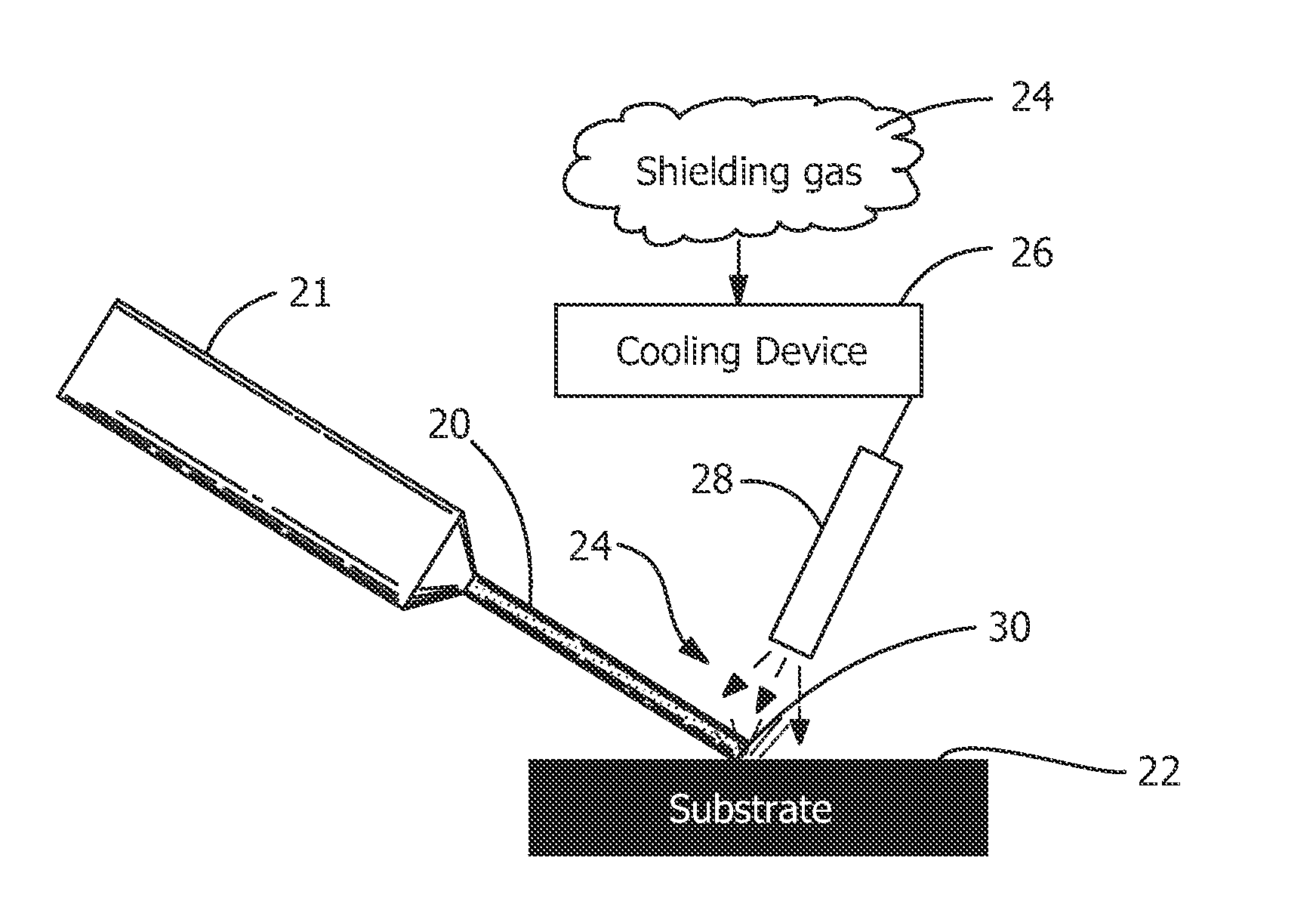
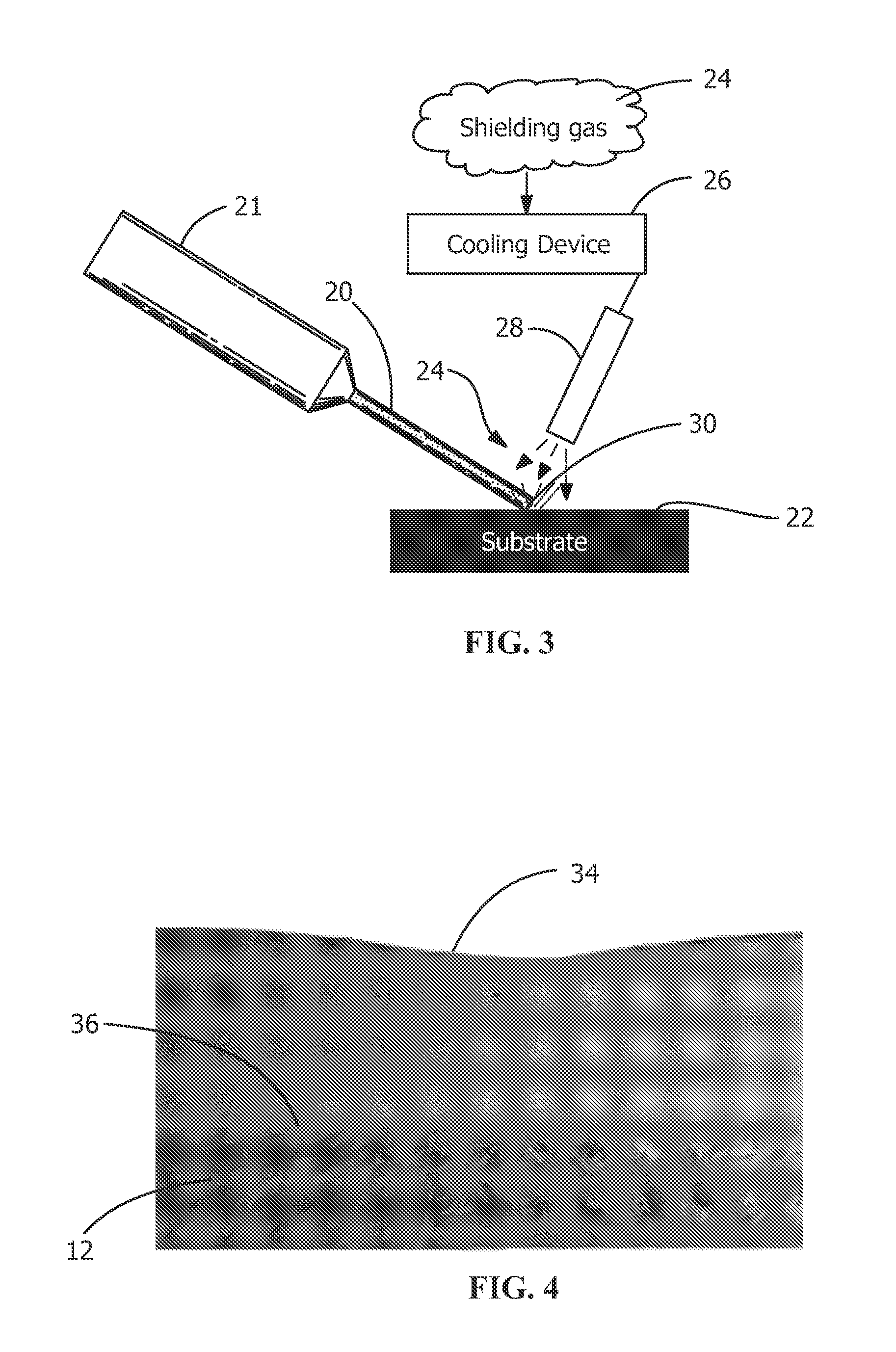
[0020]Referring next to FIG. 3, an electrospark deposition (ESD) process is shown. The ESD provides a suitable thickness of electrode material to repair the substrate, e.g., a fuel nozzle tip 12 (FIG. 1). An electrospark device 21 supports and drives a consumable electrode 20. Electrode 20 is placed into contact with a metal substrate 22, which in this example schematically represents the nozzle tip 12. Electrode 20 is composed of material suitable for forming a metallurgical bond with substrate 22. A shielding gas flow 24 is first introduced to a cooling device 26 to lower the temperature of the shielding gas flow 24 below the ambient temperature. Cooling devices for shielding gases, e.g., argon, nitrogen, or helium, are known to those skilled in the ar...


PUM

PropertyMeasurementUnit
temperatureaaaaaaaaaa
thicknessaaaaaaaaaa
temperatureaaaaaaaaaa

Abstract

A system and method for repairing a metal substrate includes an electrospark device and an electrode removably supported in the electrode holder. The electrospark device applies a coating of a material when placed into contact with the metal substrate. A cooling device to lowers the temperature of shielding gas flow below an ambient temperature. A conduit is arranged to direct a flow of the shielding gas to the interface of the electrode and the substrate to cool the area of the substrate receiving the coating.

Description

CROSS-REFERENCE TO RELATED APPLICATIONS[0001]This application is a divisional of U.S. Utility Application No. 13 / 471,617, filed on May 15, 2012, and entitled “Electrospark Deposition Process And System For Repair Of Gas Turbine”, the disclosure of which is hereby incorporated by reference in its entirety.FIELD OF THE INVENTION[0002]The application generally relates to the repair of gas turbine components. The application relates more specifically to the use of an electrospark deposition system for repair of a gas turbine primary fuel nozzle.BACKGROUND OF THE INVENTION[0003]Gas turbine engines include fuel nozzles to deliver combustion fuel to combustor components. Over a period of extended use, fuel nozzles may experience deterioration, e.g, around the edges of the nozzle tip. There is currently no efficient process available to repair a primary fuel nozzle that is manufactured with a brazed joint between the nozzle tip and the body of the nozzle. Any process to build a metal layer ...

Claims


Application Information

Patent Timeline
Patent Type & Authority Applications(United States)
IPC IPC(8): B23K9/04B23K9/173B23K9/28B23K9/29B23K9/32
CPCB23K9/044B23K9/173B23K9/32B23K9/285B23K9/291B23K9/324B23K9/164B23K37/003B23P6/007F01D5/005F05D2230/233B23K2101/001B23K9/04
Inventor LIN, DECHAOOBEIRNE, JOHN GREGORYBUCCI, DAVID VINCENTKOTTILINGAM, SRIKANTH CHANDRUDUCUI, YAN
Owner GENERAL ELECTRIC CO
Why Eureka
Try Eureka