

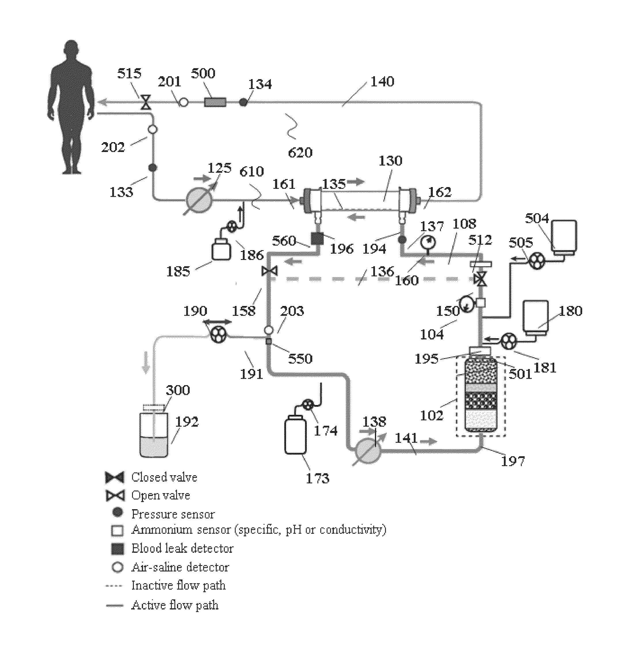
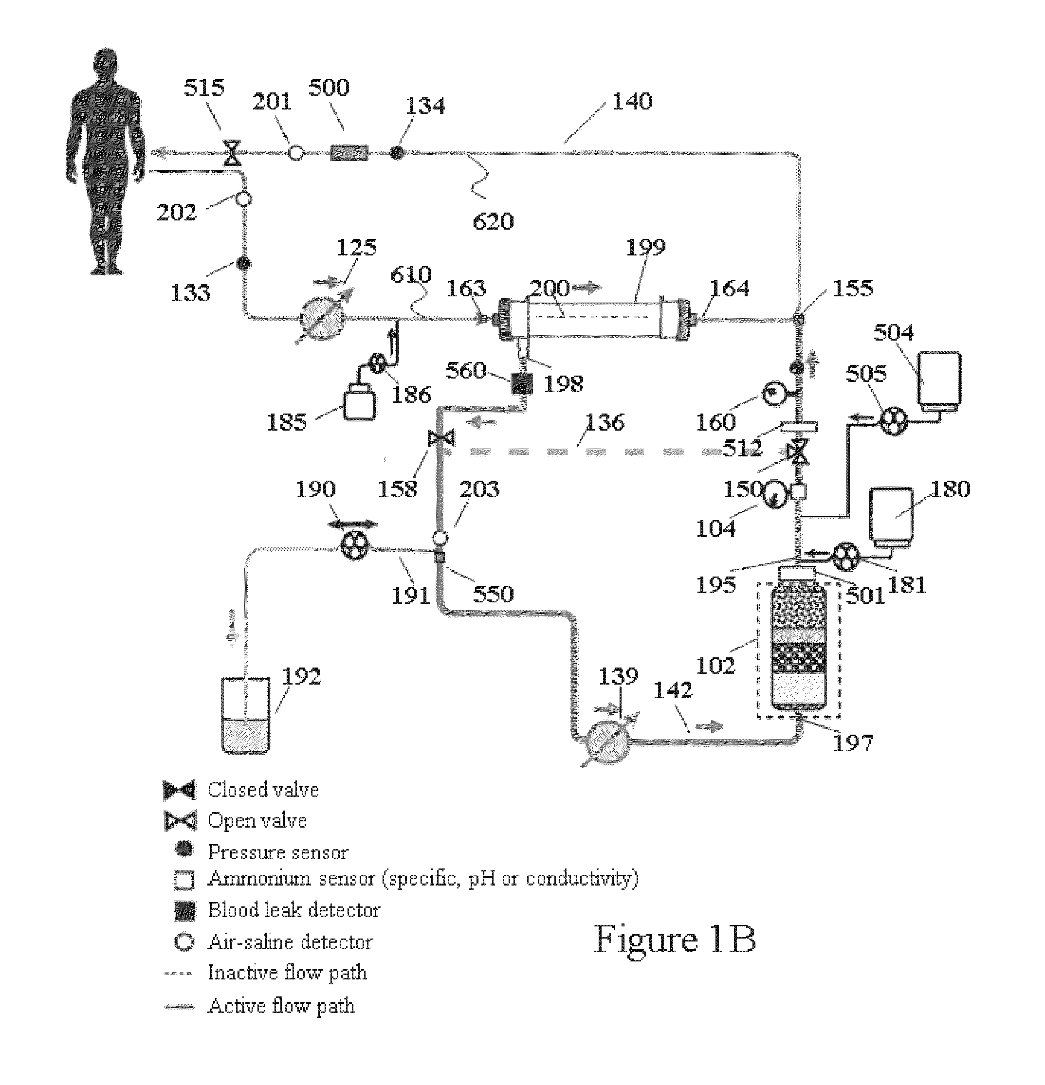
Hemodialysis system having a flow path with a controlled compliant volume
a flow path and hemodialysis technology, applied in the field of hemodialysis apparatus and hemofiltration, can solve the problems of dialysis treatment, no cure, death of all people with ckd, etc., and achieve the effect of reducing the risk of blood clotting and enhancing convective clearan
- Summary
- Abstract
- Description
- Claims
- Application Information
AI Technical Summary
Benefits of technology
Problems solved by technology
Method used
Image


Examples
Embodiment Construction
[0156]Dialysis is the most commonly applied physical principle to address the build-up of urea and other toxins, to balance electrolytes, and to remove excess fluid in patients with kidney failure. Dialysis as a renal or kidney replacement therapy can include hemodialysis, hemodiafiltration, or hemofiltration to remove toxins and impurities from a patient's blood. Dialysis membranes employed in dialysis treatment are typically only selective toward molecular weight and not toward other properties such as electrical charge. As such, urea, ions and other small molecules can move across the dialysis membrane unimpeded from a higher concentration to a lower concentration via diffusion thereby lowering the concentration of such species in the patient's blood through the process of hemodialysis.
[0157]Hemofiltration and hemodiafiltration employ techniques involving removing fluid from the patient by drawing bulk fluid across the dialysis membrane thereby pulling out waste products with a s...
PUM
| Property | Measurement | Unit |
|---|---|---|
| pressure | aaaaa | aaaaa |
| pressure | aaaaa | aaaaa |
| pressure | aaaaa | aaaaa |
Abstract
Description
Claims
Application Information