Wireless Collection and Analysis of Machine Data

a technology of machine data and collection and analysis, which is applied in the direction of wireless commuication services, machine-to-machine/machine-type communication services, instruments, etc., can solve the problems of reducing machine performance and reliability, affecting the safety of operators, so as to reduce the risk of entanglement of cables and improve the safety of operators

Active Publication Date: 2016-02-11
ACOEM FRANCE
View PDF7 Cites 43 Cited by
  • Summary
  • Abstract
  • Description
  • Claims
  • Application Information

AI Technical Summary

Benefits of technology

[0019]Advantages of the wireless sensor unit of this invention include improved operator safety while measuring vibrations from rotating parts of a machine, due to a decreased risk of entangling cables that otherwise may extend from the sensor to the data collection unit. The absence of a cable also reduces the weight of materials that the operator needs to carry around a facility when performing a machine diagnostic data collection route.
[0020]Another advantage is an improved reliability of the vibration measurements. Previously, a wired sensor has been mounted to one test point after another on each bearing of the machine and from one machine to another, until all machines to be monitored in a plant or facility have been measured. As performed for an entire factory, and then different factories in turn (and/or the same factories over again), the many mechanical solicitations of mounting and dismounting the wired sensor, along with the moving

Problems solved by technology

Because of the importance of these machines in meeting production and service requirements, taking a machine offline unexpectedly due to a failure can be costly.
Of concern is that a machine part that is moving or being moved against may result in decreased machine performance and reliability.
Eventually if a deteriorating condition is not detected a failure may occur.
Experience has revealed that the use of cables or the close proximity of the technician to the machine during data acquisition is a potential hazard.
For example, the cables can become caught or tangled in moving parts of the machine possibly injuring the technician or damaging the machine parts.
In addition

Method used


Image

  • Wireless Collection and Analysis of Machine Data
  • Wireless Collection and Analysis of Machine Data
  • Wireless Collection and Analysis of Machine Data

Examples


Embodiment Construction

[0044]In the following description, for purposes of explanation and not limitation, specific details may be set forth, such as particular terminals, devices, components, techniques, protocols, interfaces, hardware, etc. in order to provide a thorough understanding of the present invention. However, it will be apparent to one skilled in the art that the present invention may be practiced in other embodiments that depart from these specific details. Detailed descriptions of well-known computers, terminals, devices, phones, components, techniques, protocols, interfaces, and hardware are omitted so as not to obscure the description of the present invention. Accordingly, computer components and other components, protocols, and interfaces, known to one of ordinary skill in the art of machine vibration data collection and analysis are intended to be inferred into the detailed description.

Machine Diagnostic Data Collection and Analysis System

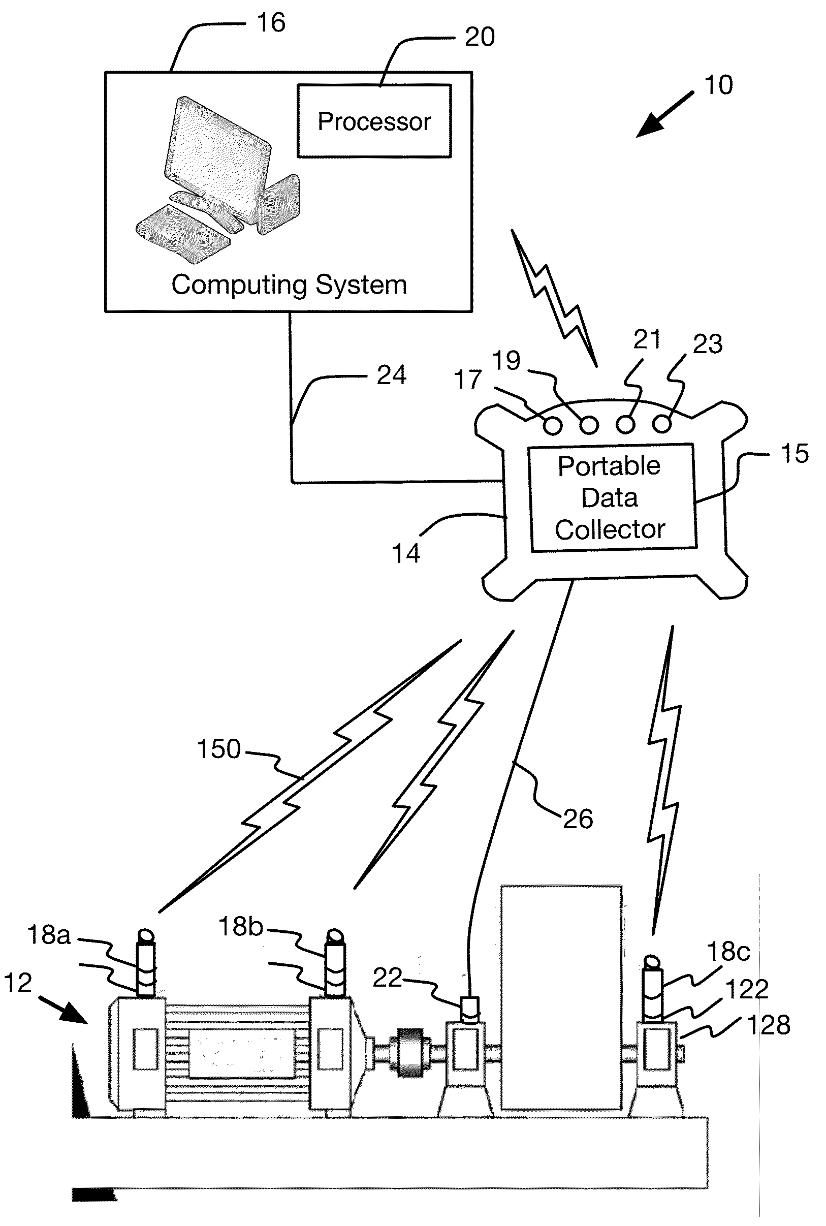
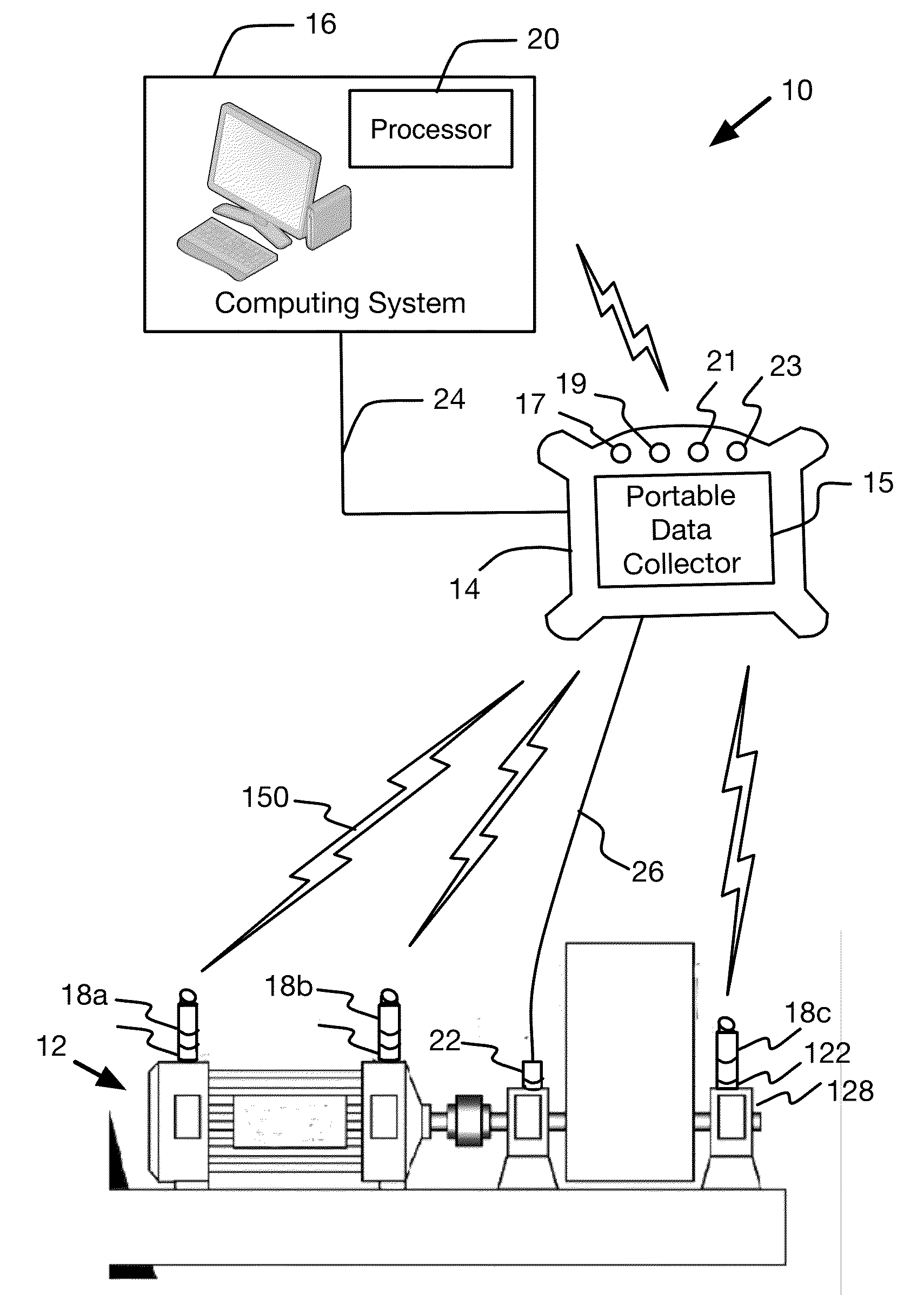
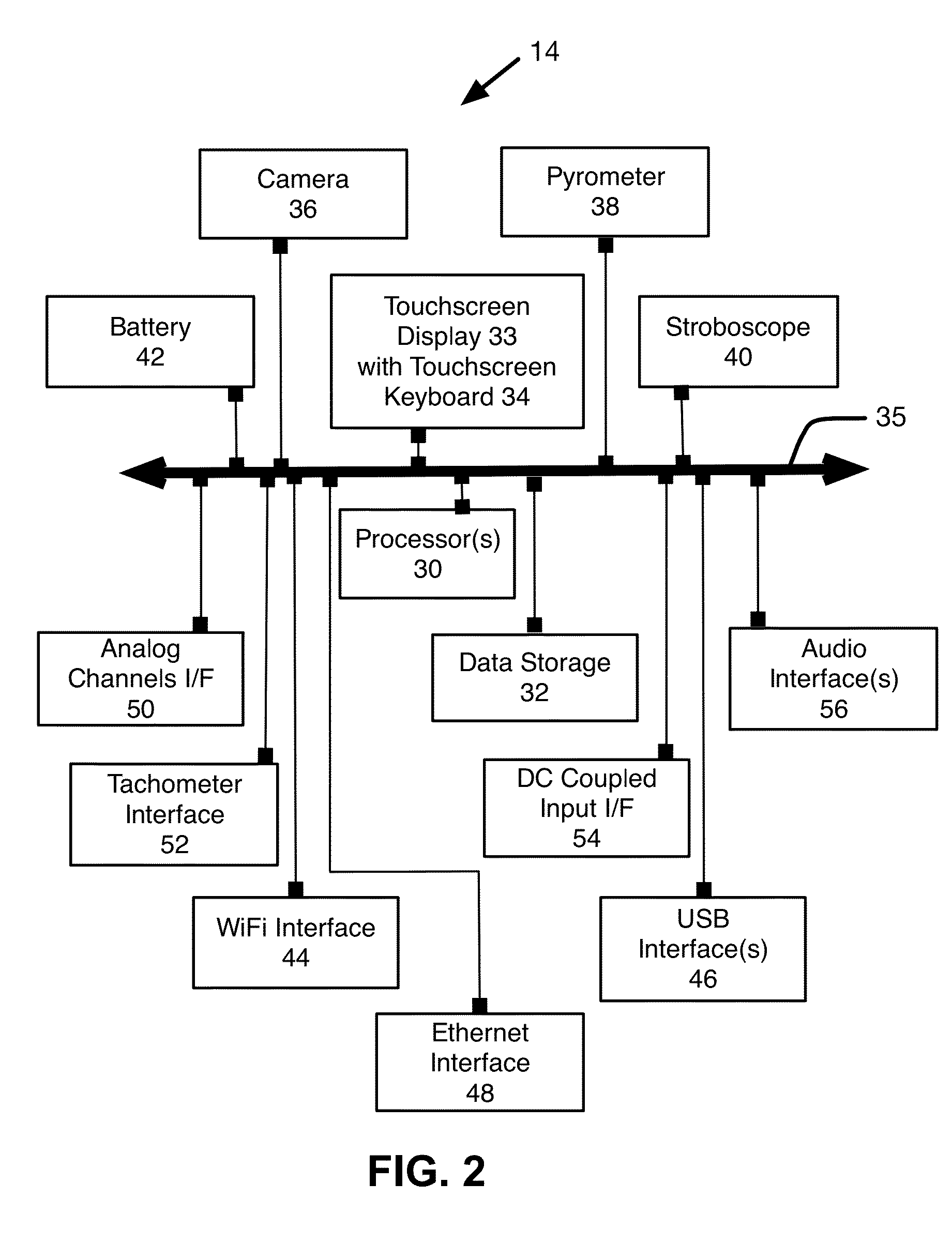
[0045]FIG. 1 shows a machine diagnostic data coll...


PUM


Abstract

A sensor unit is configured as a single body, removably mounted in its entirety to a test point location on a machine so machine vibrations propagate into the single body. Within are an accelerometer, circuit board, wireless interface, signal processor, and battery. The sensor unit transmits sensor data wirelessly in real time to a data collection unit. A technician with data collection unit in hand goes from machine to machine, along a route of multiple test point locations on multiple machines, mounting and dismounting the sensor unit and collecting machine vibration data. The sensor unit is configured to reduce frequency response impacts of the mass and volume of the circuit board, wireless interface, signal processor, and battery on dynamic behavior of the sensor unit with respect to machine vibrations to achieve a frequency response rating comparable to a wired sensor.

Description

RELATED SPECIFICATION[0001]This application is related to commonly-assigned, U.S. patent application Ser. No. ______ of Wascat et al. filed on the same day (Attorney Docket No. AC1.P102) for “Automated Rotating-Machine Fault Diagnosis with Confidence Level Indication,” and is incorporated herein in its entirety by reference.BACKGROUND OF THE INVENTION[0002]This invention relates generally to the collection and analysis of machine diagnostic data, such as vibration data, temperature, and rotation speed. More particularly, this invention relates to methods and apparatus for wireless data acquisition of machine diagnostic data for use in the automated diagnosis, and predictive maintenance of machines having moving parts.[0003]Many types of machines are used in a production or manufacturing facility, such as in the production of consumer and industrial goods and in the delivery of basic utility services. Because of the importance of these machines in meeting production and service requi...

Claims


Application Information

Patent Timeline
IPC IPC(8): G01M99/00G01P15/02H04W4/70
CPCG01M99/005H04W4/005G01P15/02H04W4/70G01D21/00
Inventor WASCAT, BERTRANDPOIZAT, PHILIPPELABEYRIE, PATRICKMAZOYER, THIERRY
Owner ACOEM FRANCE
Why Eureka
Try Eureka