Wire for deep water transmission

Active Publication Date: 2016-03-03
MATERION
View PDF10 Cites 3 Cited by
  • Summary
  • Abstract
  • Description
  • Claims
  • Application Information

AI Technical Summary

Benefits of technology

[0006]The present disclosure relates to electrically conductive wires that are suitable for use in long subsea power cables. The wire is made of a first wire portion and a second wire portion. The first wire portion is located at one end of the wire, and is made of a metal that has a higher ultimate tensile strength than the second wire portion. It is contemplated that the first wire portion, i.e.

Problems solved by technology

The need for such scaffolding can complicate the construction of the oil/gas well.
In addition, the power cable will experience large tensile forces and dynamic motion during its service lifetime, for example due to movement of waves and/or ocean currents.
The cable can also be exposed to torsional forces t

Method used


Image

  • Wire for deep water transmission
  • Wire for deep water transmission
  • Wire for deep water transmission

Examples


Embodiment Construction

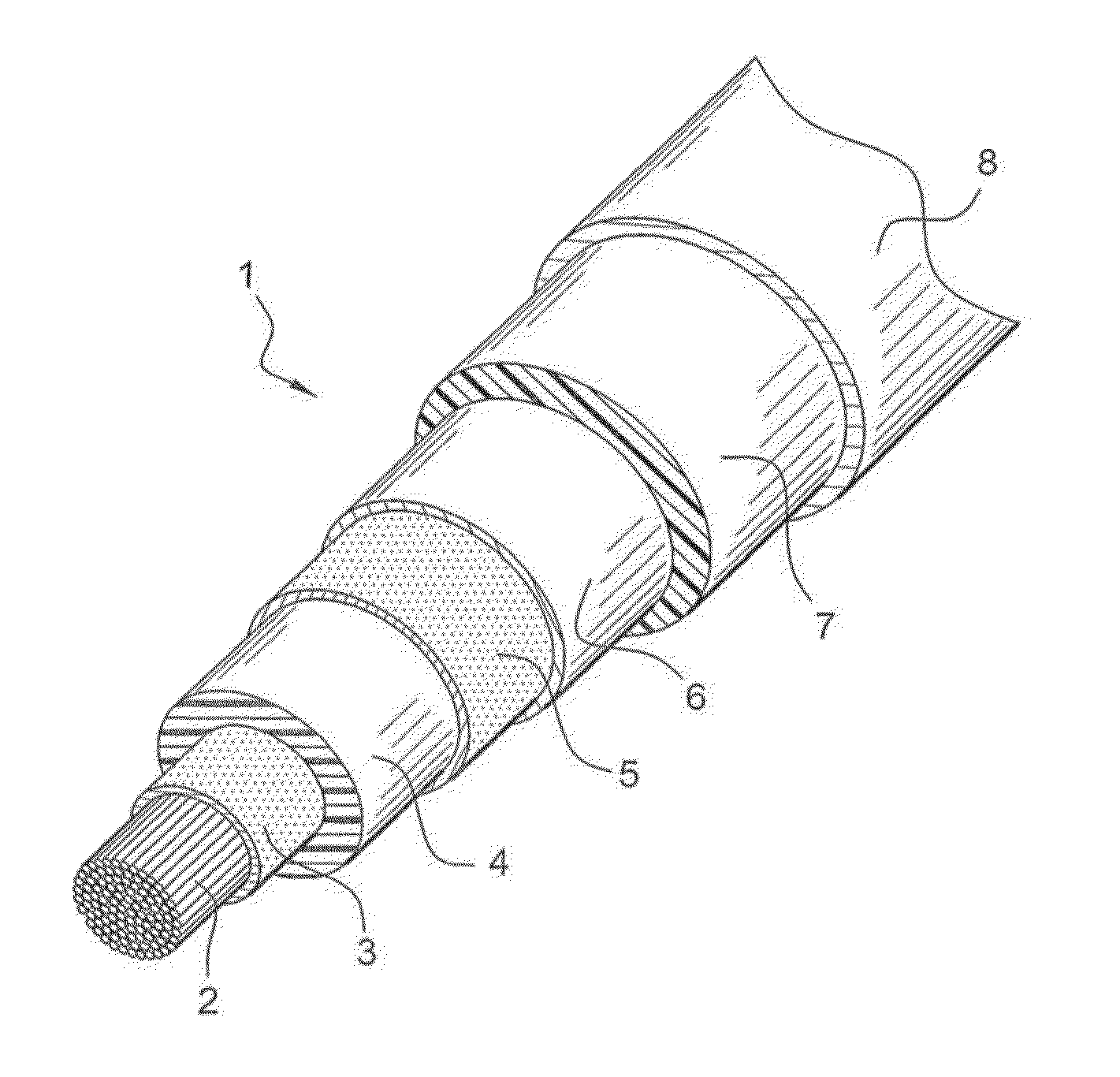
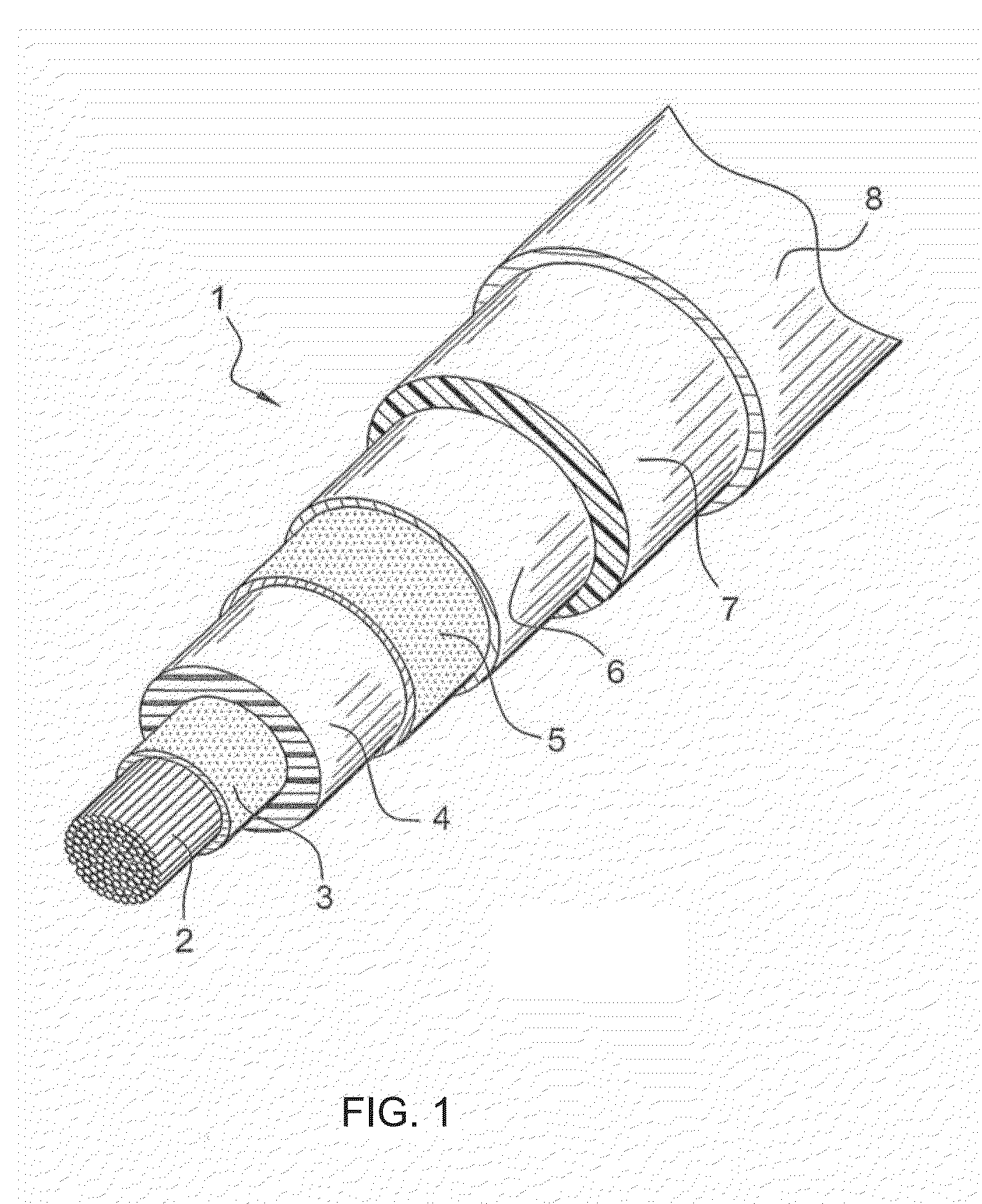
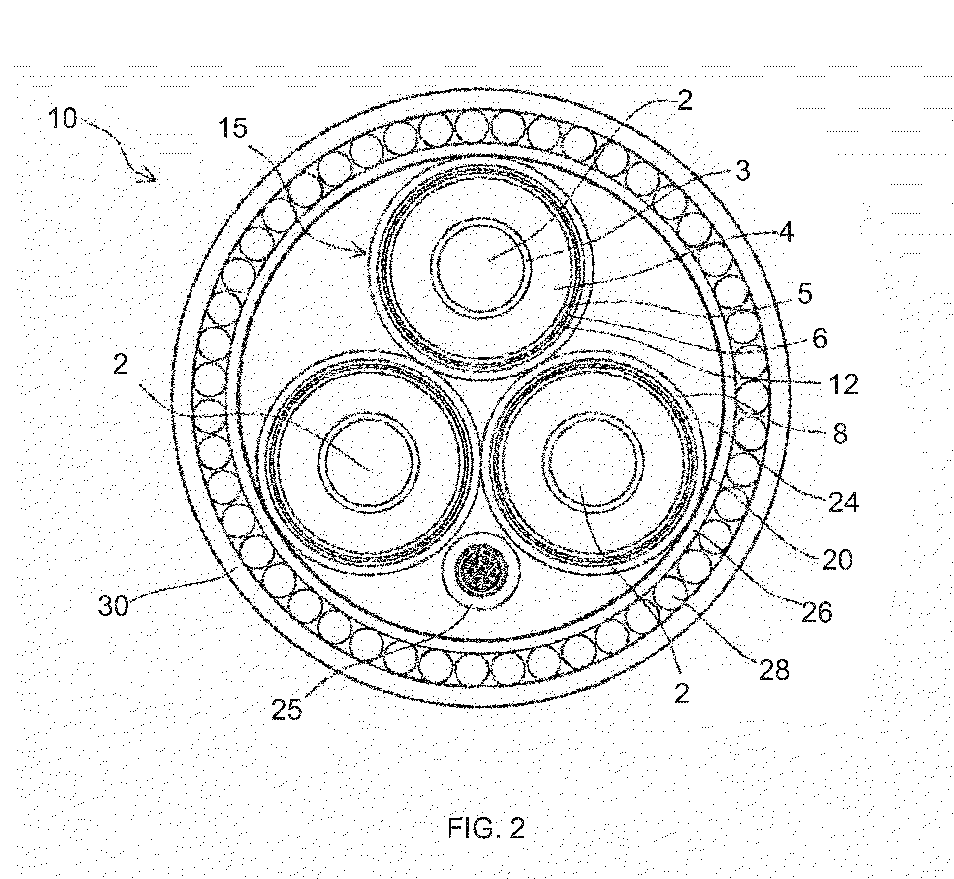
[0026]A more complete understanding of the components, processes and apparatuses disclosed herein can be obtained by reference to the accompanying drawings. These figures are merely schematic representations based on convenience and the ease of demonstrating the present disclosure, and are, therefore, not intended to indicate relative size and dimensions of the devices or components thereof and / or to define or limit the scope of the exemplary embodiments.

[0027]Although specific terms are used in the following description for the sake of clarity, these terms are intended to refer only to the particular structure of the embodiments selected for illustration in the drawings, and are not intended to define or limit the scope of the disclosure. In the drawings and the following description below, it is to be understood that like numeric designations refer to components of like function.

[0028]The singular forms “a,”“an,” and “the” include plural referents unless the context clearly dictat...


PUM


Abstract

An electrically conductive wire for deep water transmission includes a first wire portion and a second wire portion. The first wire portion makes up one end of the wire, and is formed from a first metal. The second wire portion is formed from a second metal. The first metal has a higher ultimate tensile strength than the second metal. The first wire portion is used to support the weight of the second wire portion, thereby allowing the electrically conductive wire to be used in underwater or subsea power cables which may be freely suspended from their origin for providing electricity to electrical devices located in deep water or ultra-deep water.

Description

CROSS-REFERENCE TO RELATED APPLICATIONS[0001]This application claims priority to U.S. Provisional Patent Application Ser. No. 62 / 040,272, filed Aug. 21, 2014, the entirety of which are fully incorporated by reference herein.BACKGROUND[0002]The present disclosure relates to electrically conductive wires. The electrically conductive wires are particularly useful for long power cables, such as those used to provide electricity to deep water devices.[0003]Subsea oil and gas wells may be located in ultra-deep water devices (depths of 1500 meters or greater, ˜5000 feet). Providing electricity to subsea devices at this depth requires suspending very long power cables from a surface location at sea to a terminal location on the sea floor. The weight of these power cables is largely borne at the end of the power cable secured to the surface location. The power cables are also affixed to riser tubing / scaffolding coming up from the sea floor to bear the weight of the cable. The need for such s...

Claims


Application Information

Patent Timeline
IPC IPC(8): H01B7/14H01B1/02H01B3/00H01B5/02H01B7/282H01B9/00H01B9/02
CPCH01B7/14H01B1/026H01B1/02H01B3/004H01B9/006H01B9/02H01B7/2825H01B5/02H01B7/045Y02A30/14
Inventor NIELSEN, JR., WILLIAM, D.NIELSEN, DIANE, M.MAXWELL, WALTER, G.
Owner MATERION
Why Eureka
Try Eureka