
Bioresorbable biopolymer stent

Inactive Publication Date: 2016-03-10
TUFTS MEDICAL CENTER INC +1
View PDF7 Cites 16 Cited by
  • Summary
  • Abstract
  • Description
  • Claims
  • Application Information

AI Technical Summary

Benefits of technology

The present invention is about the use of resorbable stents to replace permanent implants and treat temporary physiological problems. These stents are made of biopolymers that can be resorbed by the body, reducing the risk of complications like blood clots and the need for long-term antiplatelet drugs. The use of biopolymers also allows for more complex drug release and the delivery of multiple drugs over several time scales. Additionally, these stents do not produce any metallic artifacts that may interfere with diagnostic imaging. Overall, this innovation offers greater control, customization, and integration with the body's own cells, making them better suited for use in regenerative medicine and tissue engineering.

Problems solved by technology

The continued presence of the stent becomes unnecessary and in some cases becomes deleterious.
Current stent technology permanently remains in the vessel, which introduces many limitations including the risk of early and late thrombosis requiring the permanent use of P2Y12 inhibitors for antiplatelet drug treatment (see Van Belle et al, Drug-eluting stents: trading restenosis for thrombosis?, J Thrombosis and Haemostasis, 2007, Suppl 1(January):238-245).
A completely resorbable yet mechanically sufficient drug-eluting polymer stent that meets clinical applications of current metallic stents is not commercially available.
Medication coated stents reduce the risk of restenosis and blood clots, but current metal stents only facilitate limited release.
This procedure is often complicated by vessel recoil and restenosis and requires a stent for support.
The balloon-mounted deployment system requires expansion to be hastened by dilatation with contrast medium at a temperature of 80° C., which makes use cumbersome (see Nishio et al).
However, initial trials produced higher than expected intimal hyperplasia and restenosis necessitating design revisions (see Ormiston and Serruys).
However, high rates of restenosis in the results of the PROGRESS AMS trial suggest loss of radial support during absorption happens prematurely (see Waksman et al., Early- and long-term intravascular ultrasound and angiographic findings after bioabsorbable magnesium stent implantation in human coronary arteries, JACC, 2009, 2(4): 312-320).
This may lead to an insufficient radial strength to counter the force of early remodeling (see Gonzalo and Macaya).
Metal drug-eluting stents are limited to a thin polymer matrix for drug delivery.
While modern metallic approaches offer initial strength and degradability, the degradation of alloys such as magnesium results in pronounced surface pitting which limits their use as implant material.

Method used


Image

  • Bioresorbable biopolymer stent
  • Bioresorbable biopolymer stent
  • Bioresorbable biopolymer stent

Examples


first embodiment

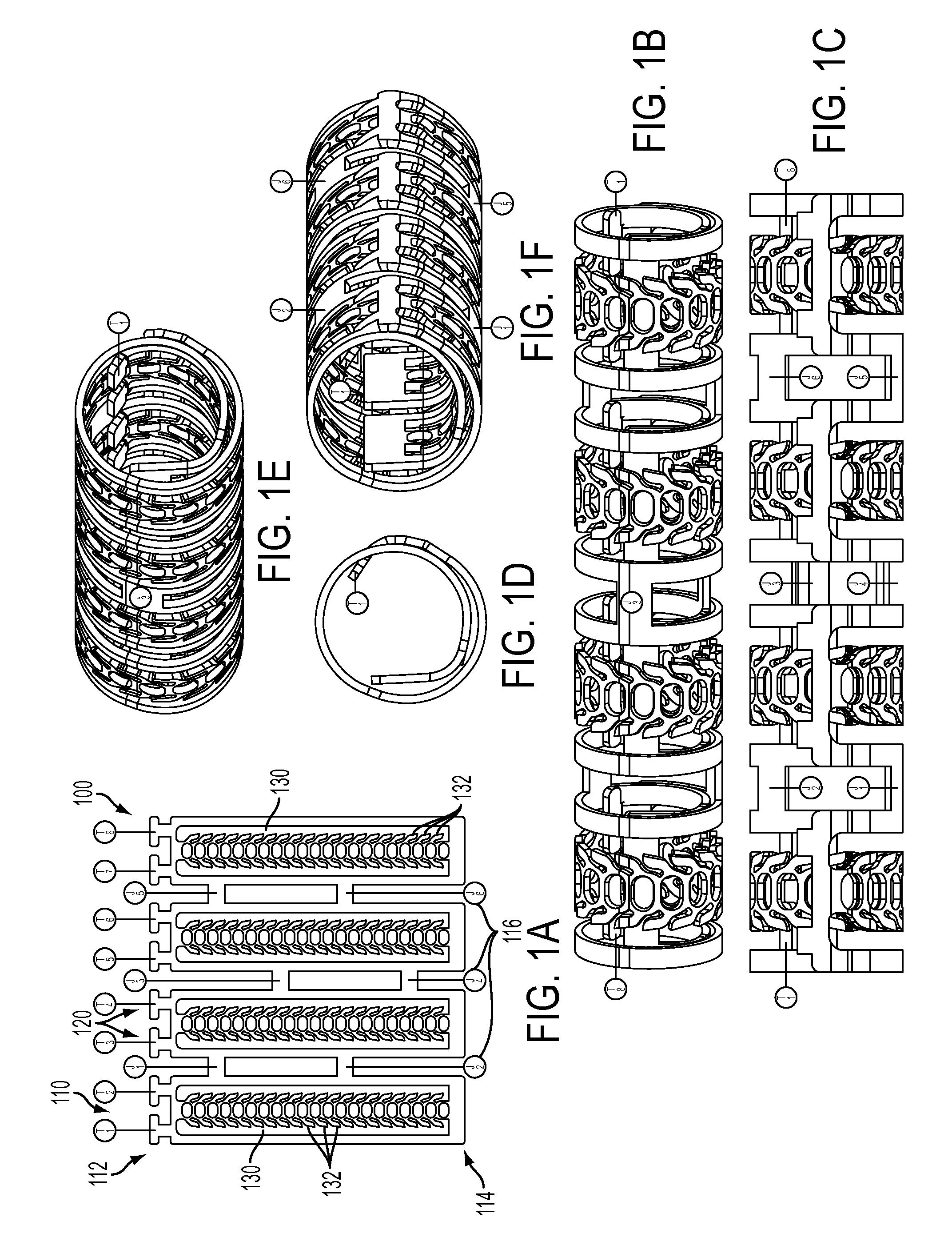
[0041]FIGS. 1A-1F show a ratcheting polymer stent 100 according to the invention. The stent 100 can include one or more stent elements 110, for example, FIGS. 1A-1F show four stent elements 110, each being connected or joint to one or more adjacent stent elements 110 by a joint 116. The joints 116 can be cut to enable the axial length of the stent 100 to be reduced. Each stent element 110 can include a first end 112 and a second end 114. The first end 112 can include one or more tabs 120 that are adapted to fit into slots 130. The slots 130 can extend from the second end 114 toward the first end 112 and while the figure shows the slot 130 extending all the way to the first end 112, the slot can end before reaching the first end 112, for example, ending in the middle of the device. The slot 130 can also include one or more teeth 132 that interact with tab 120 to control the diameter of the stent 100. The teeth 132 can be configured with an angled surface that allows the tab 120 to mo...

second embodiment

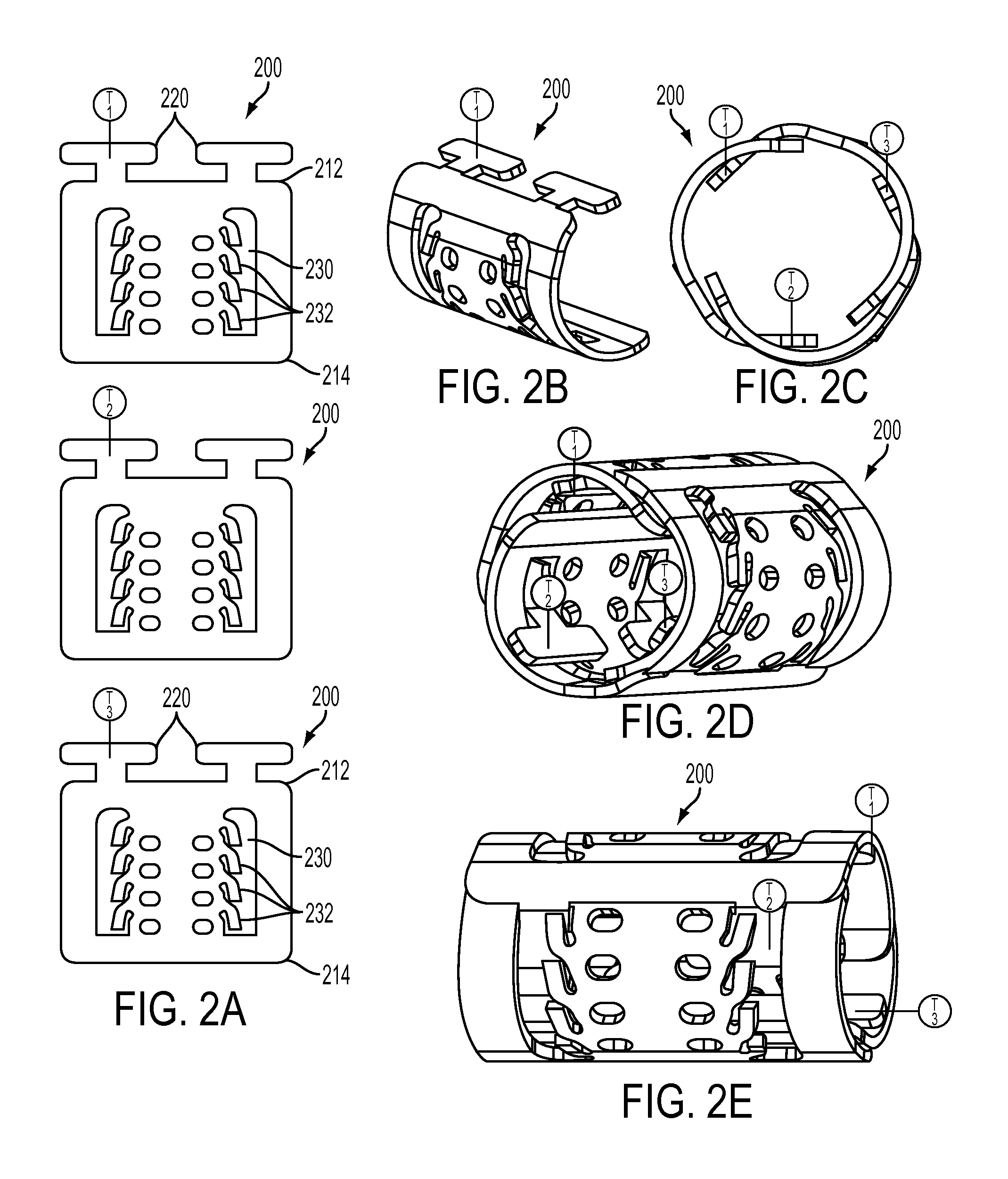
[0044]FIGS. 2A-2E show a ratcheting polymer stent 200 according to the invention. The stent 200 can be formed by combining two or more stent elements 210 in an end to end configuration as shown in FIGS. 2B-2E. While these figures show three, relatively short stent elements 210 connected end to end for form a hollow tube more stent elements 210 can be used to produce a larger diameter stent 200 and longer stent elements 210 can be used to enable larger variations in expanded stent diameter. Stent elements 210 of differing lengths can be used together. In this embodiment, each stent element 210 can be similar in the stent elements 110 shown in FIGS. 1A-1F. Thus each stent element 210 can include a first end 212 and a second end 214, the first end 212 can include one or more tabs 220 that are adapted to fit into slots 230. The slots 230 extend from the second end 214 toward the first end 212 and while the figure shows the slot 230 extending all the way to the first end 212, the slot ca...

third embodiment

[0047]FIGS. 3A-3C show a ratcheting polymer stent 300 according to the invention. The stent 300 can include one or more stent elements 310, for example, FIGS. 3A and 3C show four stent elements 310, each being connected or joint to one or more adjacent stent elements 310 by a common side or joint 316. The joints 316 can be cut to enable the axial length of the stent 300 to be reduced. Each stent element 310 can include a first end 312 and a second end 314, and the first end 112 can include one or more tongues or strips 330 that are adapted to fit into slots 320. The strips 330 extend from first end 312 to the second end 314. The strip 330 can also include one or more teeth 332 that interact with slot 320 to control the diameter of the stent 300. The teeth 332 can be configured with an angled surface that allows the slot 320 to more easily slide past the teeth 332 in one direction (e.g. to increase in diameter) but resist movement in the opposite direction (e.g. to resist compressive...


PUM

PropertyMeasurementUnit
Fractionaaaaaaaaaa
Fractionaaaaaaaaaa
Timeaaaaaaaaaa

Abstract

A bioresorbable biopolymer stents can be deployed within a blood vessel and resorbed by the body over a predetermined time period after the blood vessel has been remodeled. A ratcheting biopolymer stent can include a ratcheting mechanism that allows the biopolymer stent to be deployed on a small diameter configuration and then expanded to a predefined larger diameter configuration wherein after expansion, the ratcheting mechanism locks the biopolymer stent in the expanded configuration. A folding biopolymer stent can be deployed in a folded, small diameter configuration and then expanded to an unfolded configuration having a larger diameter. The bioresorbable biopolymer can include silk fibroin and blend that include silk fibroin materials.

Description

CROSS-REFERENCE TO RELATED APPLICATIONS[0001]This application claims priority to U.S. provisional patent application Ser. No. 61 / 815,519, filed on Apr. 24, 2013, the disclosure of which is hereby incorporated in its entirety.STATEMENT REGARDING FEDERALLY SPONSORED RESEARCH[0002]This invention was made with government support under grant EB002520 awarded by the National Institutes of Health. The government has certain rights in the invention.BACKGROUND[0003]1. Technical Field of the Invention[0004]The invention is directed to bioresorbable biopolymer stents and methods and systems for deploying these stents. Specifically, the invention is directed to ratcheting and unfolding bioresorbable biopolymer stents that provide for increased diameter. The bioresorbable biopolymer can include silk fibroin and blend that include silk fibroin materials.[0005]2. Description of the Prior Art[0006]Stents provide an immediate mechanical opening which improves vessel patency and prevents restenosis a...

Claims


Application Information

Patent Timeline
IPC IPC(8): A61F2/844A61F2/93
CPCA61F2/93A61F2/844A61F2002/825A61F2220/0033A61F2210/0004A61F2250/0067A61F2210/0076A61F2002/826A61F2/958A61L31/005A61L31/047A61L31/141A61L31/148A61L31/16A61L2300/416A61F2/9517
Inventor JOSE, RODRIGOKAPLAN, DAVID L.IAFRATI, MARKGIL, EUN SEOKLEISK, GARY G.
Owner TUFTS MEDICAL CENTER INC
Learn More