Photo-chemically activated micro-bubble based root canal disinfection

Active Publication Date: 2016-03-10
SYACT INT LLC
View PDF14 Cites 25 Cited by
  • Summary
  • Abstract
  • Description
  • Claims
  • Application Information

AI Technical Summary

Benefits of technology

[0017]When the micro-bubble solution is mechanically activated, for example, sonically or ultrasonically, the micro-bubble solution releases oxygen bubbles. This rapid release of oxygen bubble and energy imparted to the micro-bubble solution by the sonic/ultrasonic activation markedly increases the rate of release of singlet oxygen, which in turn enhances the antimicrobial efficacy of photodynamic therapy. The sonic/ultrasonic activation of the micro-bubble solution in the root canal generates bubble/canal wall interactions throughout the axial length of the canal to mechanically disrupt the biofilm and canal debris. Additionally, the micro-bubbles scatter the light within the canal and introduce or otherwise direct light into the dentinal tubules and lateral canals, which would not otherwise be exposed to axially directed light. Thus, the lig

Problems solved by technology

Infection of the root canal and associated regions of tooth, generally known as root canal infection/endodontic infection, is a widespread problem all over the world.
If the periodontitis cannot be managed, the tooth will be lost and will need to be extracted.
Complete disinfection of the root canal is rarely achieved, although in most cases the disease symptoms recede.
The biofilm (especially the biofilm in the microtubules) thus can be difficult to target chemically or to mechanically disrupt effectively.
However, sodium hypochlorite can react with tissue remnants and the dentin in the canal, and can adversely affect the canal if left in the canal for too long.
Failure of conventional treatment is mostly due to the persistence of bacterial population even after chemo-mechanical disinfection.
Limitations in conventional treatment procedures are attributed to its inability to reach bacterial biofilm, especially in anatomically inaccessible regions of tooth.
The primary limitation of current RCT methods is the inability of thes

Method used


Image

  • Photo-chemically activated micro-bubble based root canal disinfection
  • Photo-chemically activated micro-bubble based root canal disinfection
  • Photo-chemically activated micro-bubble based root canal disinfection

Examples


Embodiment Construction

[0057]The following detailed description illustrates the invention by way of example and not by way of limitation. This description will clearly enable one skilled in the art to make and use the claimed invention, and describes several embodiments, adaptations, variations, alternatives and uses of the claimed invention, including what I presently believe is the best mode of carrying out the claimed invention. Additionally, it is to be understood that the claimed invention is not limited in its application to the details of construction and the arrangements of components set forth in the following description or illustrated in the drawings. The claimed invention is capable of other embodiments and of being practiced or being carried out in various ways. Also, it is to be understood that the phraseology and terminology used herein is for the purpose of description and should not be regarded as limiting.

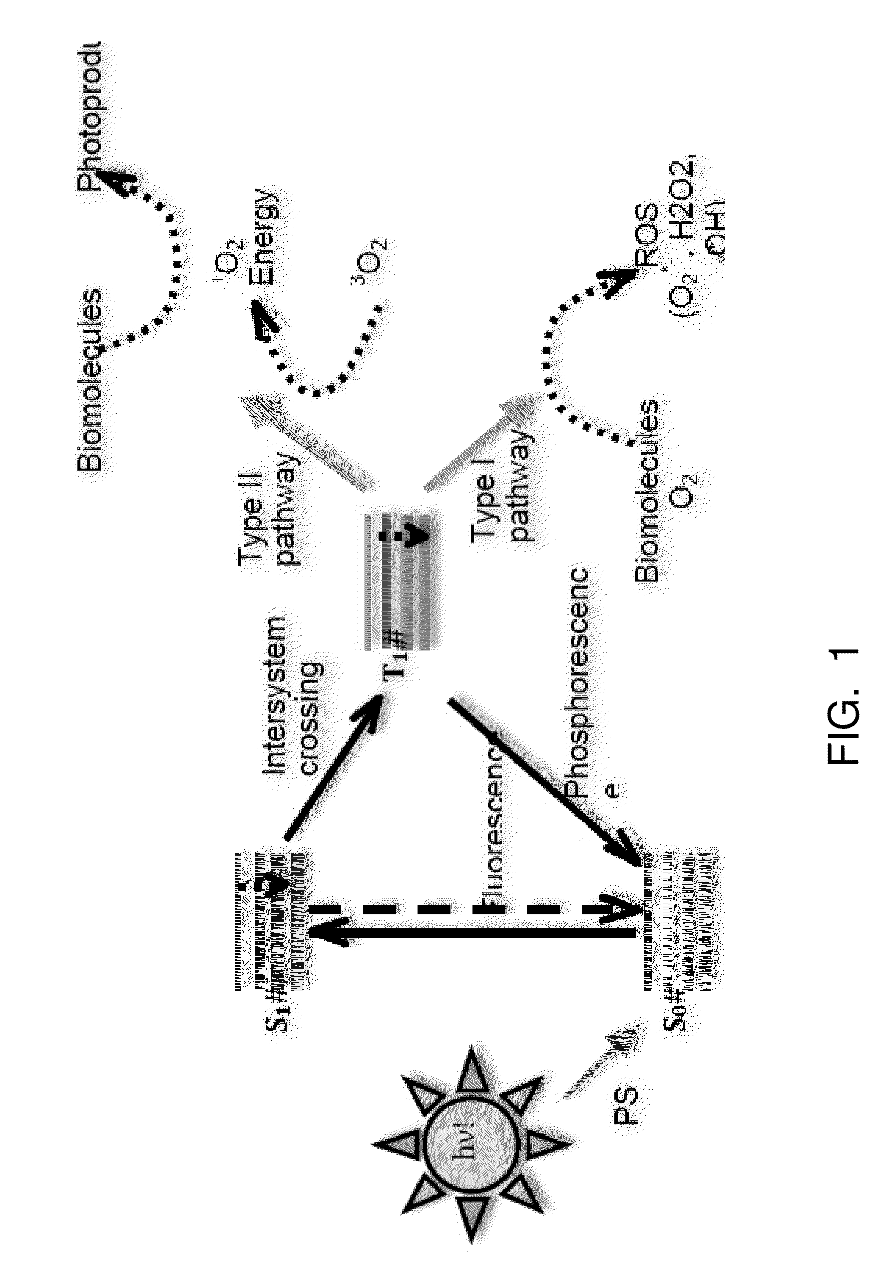
[0058]My disinfection method is shown schematically in FIG. 1. Briefly, the root ca...


PUM

PropertyMeasurementUnit
Timeaaaaaaaaaa
Nanoscale particle sizeaaaaaaaaaa
Timeaaaaaaaaaa

Abstract

A photo-chemically activated micro-bubble based root canal disinfection method for disinfecting a shaped root canal comprises (a) introducing a photoactive solution into the root canal, the photoactive solution containing a photoactive compound (such as methylene blue) dissolved in an alcohol carrier solution (such as polyethylene glycol and/or ethanol); (b) removing excess photoactive solution from the root canal; (c) introducing a micro-bubble solution comprised of an oxygen carrier (such as perfluorocarbon), an oxidizing agent (such as hydrogen peroxide) and a surfactant (such as a nonionic polyoxyethylene surfactant); (d) sonically or ultrasonically activating the micro-bubble solution in the canal; and (e) introducing light into the canal.

Description

CROSS-REFERENCE TO RELATED APPLICATIONS[0001]Not Applicable.STATEMENT REGARDING FEDERALLY SPONSORED RESEARCH OR DEVELOPMENT[0002]Not Applicable.BACKGROUND OF THE INVENTION[0003]The present invention relates broadly to disinfection of root canals during endodontic, or root canal, procedures, and in particular to the use of micro-bubbles which when mechanically activated, for example, with ultrasonic / sonic energy improve the micro-bubble pulsations / interaction with the root canal wall (mechanical effect) and simultaneously enhance the efficacy of light activated disinfection (antibacterial effect).[0004]Apical periodontitis is defined as an inflammatory process around the tooth root-apex, and is primarily a sequel to microbial infection (mainly bacteria) of the root-canal space of the tooth. Infection of the root canal and associated regions of tooth, generally known as root canal infection / endodontic infection, is a widespread problem all over the world. It represents a localized inf...

Claims


Application Information

Patent Timeline
IPC IPC(8): A61K6/00A61C5/04A61M37/00A61N5/06
CPCA61K6/0035A61C5/04A61N5/0603A61N5/062A61N2005/067A61M37/0092A61N2005/0606A61N2005/0651A61N2005/0654A61N5/0624A61N2005/0644A61C5/50A61K6/62A61K6/52A61K6/20A61P1/02A61P31/02A61N5/067A61K41/0057
Inventor KISHEN, ANIL
Owner SYACT INT LLC
Why Eureka
Try Eureka