Rotary blade tip

a technology of rotary blades and blades, applied in the direction of blade accessories, machines/engines, waterborne vessels, etc., can solve the problems of reducing engine efficiency, mechanical and thermal damage to blades, reducing engine efficiency, etc., and achieve the effect of increasing the oxidation resistance of the second abrasive coating

Inactive Publication Date: 2016-03-10
ROLLS ROYCE PLC
View PDF2 Cites 14 Cited by
  • Summary
  • Abstract
  • Description
  • Claims
  • Application Information

AI Technical Summary

Benefits of technology

[0024]The abrasive particles in the second abrasive coating may be embedded into the second matrix to a greater extent than the first abrasive particles (e.g. cubic boron nitride partic

Problems solved by technology

It is desirable to reduce the clearance between the tip of a rotary turbine blade and the turbine casing of a gas turbine engine in order to prevent air flow from by-passing the rotary blade which reduces engine efficiency.
However, minimising the clearance between the turbine blade tip and the turbine casing can lead to undesirable rubbing of the turbine blade tips on the turbine casing, which, in turn, can lead to mechanical and thermal damage to the blade due to friction and shear stresses.
Over time, this coating is depleted through rubbing against the turbine casing and may degrade through oxidation both of which increase the clearance between the blade tip and the turbine casing thus reducing engine efficiency.
Furthermore, once

Method used


Image

  • Rotary blade tip
  • Rotary blade tip
  • Rotary blade tip

Examples


Embodiment Construction

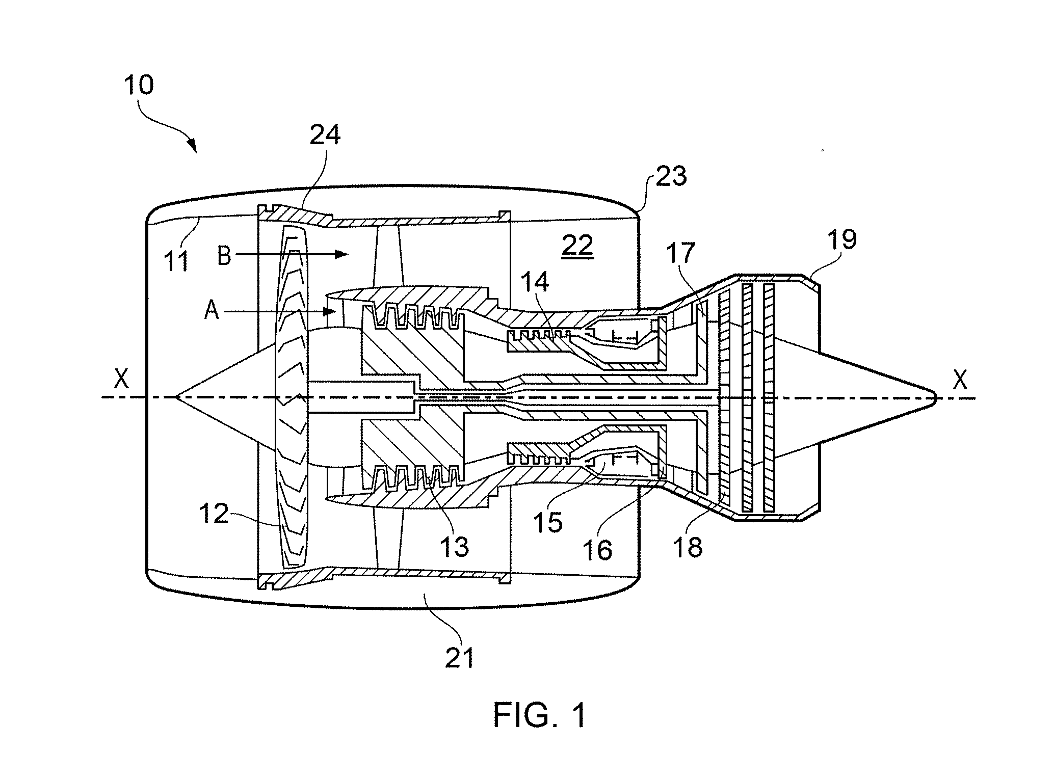
[0039]With reference to FIG. 1, a ducted fan gas turbine engine incorporating the invention is generally indicated at 10 and has a principal and rotational axis X-X. The engine comprises, in axial flow series, an air intake 11, a propulsive fan 12, an intermediate pressure compressor 13, a high-pressure compressor 14, combustion equipment 15, a high-pressure turbine 16, an intermediate pressure turbine 17, a low-pressure turbine 18 and a core engine exhaust nozzle 19. A nacelle 21 generally surrounds the engine 10 and defines the intake 11, a bypass duct 22 and a bypass exhaust nozzle 23.

[0040]During operation, air entering the intake 11 is accelerated by the fan 12 to produce two air flows: a first air flow A into the intermediate pressure compressor 13 and a second air flow B which passes through the bypass duct 22 to provide propulsive thrust. The intermediate pressure compressor 13 compresses the air flow A directed into it before delivering that air to the high pressure compres...


PUM

PropertyMeasurementUnit
Lengthaaaaaaaaaa
Lengthaaaaaaaaaa
Pressureaaaaaaaaaa

Abstract

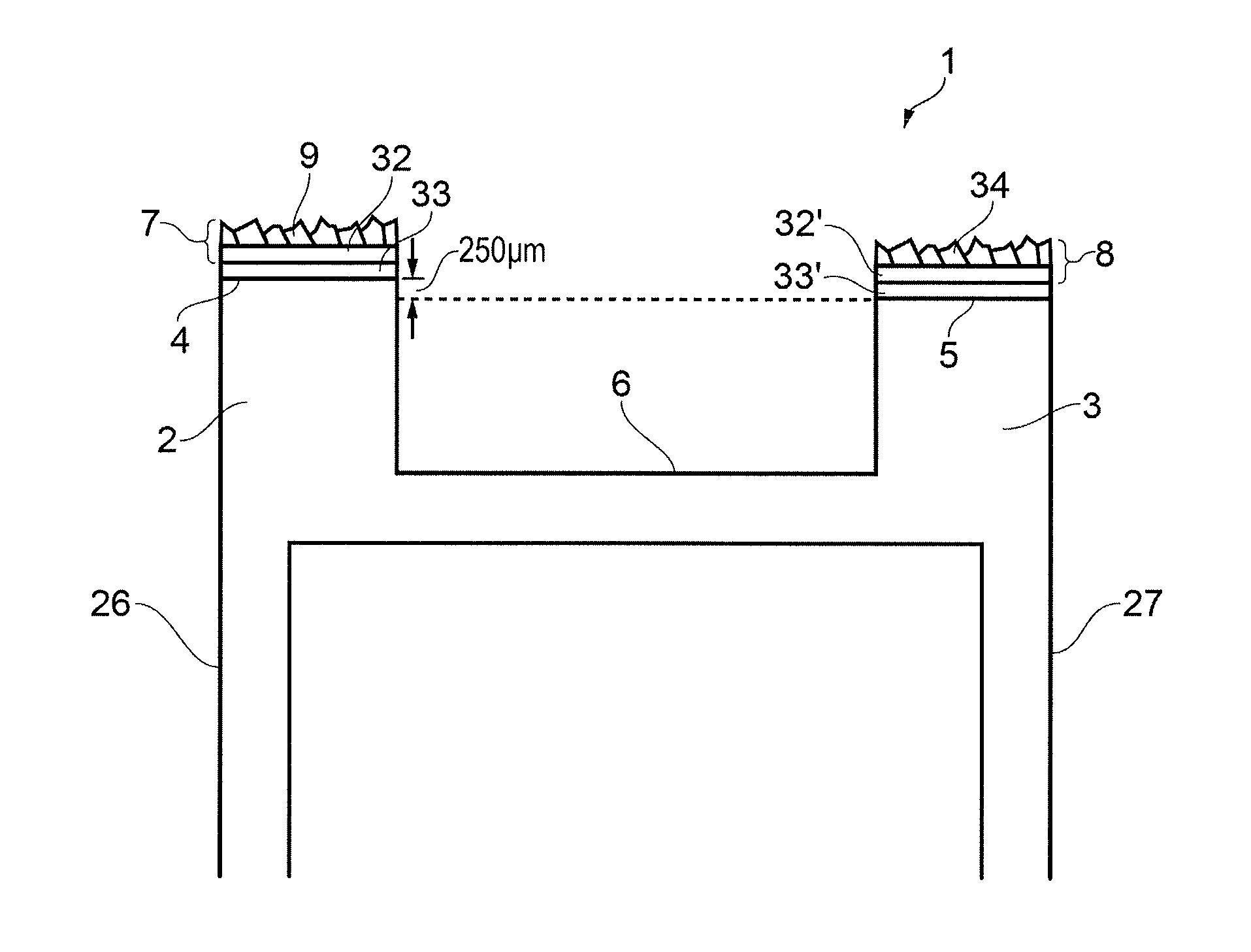
The present invention provides a blade tip for a rotary blade, the blade tip comprising a first portion and a radially-recessed second portion. A radially outermost surface of the first portion comprises a first abrasive coating e.g. a composite material comprising cubic boron nitride embedded in a matrix of nickel alloy. A radially outermost surface of the second portion comprises a second abrasive coating which has a greater resistance to oxidation than the first abrasive coating. The increased oxidation resistance of the second abrasive coating is achieved by providing a radially outer protective layer and/or using a material having a greater inherent oxidation resistance.

Description

FIELD OF THE INVENTION [0001]The present invention relates to a turbine blade tip for incorporation into a rotary blade, for example, a rotary turbine blade in a gas turbine engine.BACKGROUND OF THE INVENTION[0002]It is desirable to reduce the clearance between the tip of a rotary turbine blade and the turbine casing of a gas turbine engine in order to prevent air flow from by-passing the rotary blade which reduces engine efficiency. However, minimising the clearance between the turbine blade tip and the turbine casing can lead to undesirable rubbing of the turbine blade tips on the turbine casing, which, in turn, can lead to mechanical and thermal damage to the blade due to friction and shear stresses.[0003]It is known to provide a track liner on the interior surface of the turbine casing to provide a shroud for the turbine blade tips. The track liner is formed of an abradable material (e.g. a felt metal-filled honeycomb or ceramic coating) which is abraded by the blade tips to for...

Claims


Application Information

Patent Timeline
IPC IPC(8): F01D5/28
CPCF01D5/288F05D2220/32F05D2240/307F05D2240/31F05D2260/95F05D2300/6032F05D2300/132F05D2300/611F05D2300/2261F05D2300/2283F05D2300/173F05D2300/177F05D2300/6033F01D5/20F01D11/122
Inventor HEWITT, ANDREWHANCOCK, MATTHEWPALLETT, LLOYD
Owner ROLLS ROYCE PLC
Why Eureka
Try Eureka