Window material for ultraviolet-ray-emitting element and method for producing same

a technology of ultraviolet light and window material, which is applied in the field of window material for can solve the problems of low thermal conductivity of approximately 1 w/mk, inability to efficiently release device heat, and high temperature of ultraviolet light emitting devices using quartz, and achieves increased surface roughness of the other surface, increased surface roughness, and increased surface roughness.

Inactive Publication Date: 2016-04-07
NGK INSULATORS LTD
View PDF1 Cites 7 Cited by
  • Summary
  • Abstract
  • Description
  • Claims
  • Application Information

AI Technical Summary

Benefits of technology

[0020][10] Alternatively, the method may further include the step of increasing at least a surface roughness of the other surface of the substrate. In this step, at least the other surface of the substrate may be ground. Alternatively, the green body may be sintered while different types of setters are in contact respectively with the one surface and the other surface of the green body. For example, one setter that is in contact with the other surface may have a surface roughness larger than that of another setter that is in contact with the one surface, and thus the other surface of the substrate may have a larger surface roughness.
[0021][11] Alternatively, the method may further include the step of mirror-polishing the one surface of the substrate to obtain a surface roughness Ra of 0.03 μm or less, and the step of increasing a surface roughness of the other surface of the substrate. In this step, at least the other surface of the substrate may be ground. Alternatively, in the sintering of the green body, one of the setters that is in contact with the other surface of the green body may have a surface roughness larger than that of another setter that is in contact with the one surface, and thus the other surface of the substrate may have a larger surface roughness. Then, the one surface of the substrate may be mirror-polished to obtain the surface roughness Ra of 0.03 μm or less.
[0022]The window material of the present invention can exhibit a high transmittance of an ultraviolet light having a wavelength of 300 nm or less, and can be suitable for use in the ultraviolet light emitting device. Furthermore, the translucent alumina substrate has a high thermal conductivity of 30 W / m·K or more, and thus can efficiently release heat generated in operation of the ultraviolet light emitting device. Consequently, the window material can prevent the ultraviolet light emitting device from being broken or deteriorated due to temperature rise.
[0023]Furthermore, the method of the present invention is capable of easily producing the window material, which can exhibit a high transmittance of an ultraviolet light having a wavelength of 300 nm or less and can efficiently release heat generated in operation of the ultraviolet light emitting device.

Problems solved by technology

However, the quartz has a low thermal conductivity of approximately 1 W / m·K, and cannot efficiently release the heat of the device.
Therefore, the ultraviolet light emitting device using the quartz is likely to have a high temperature and to be broken or deteriorated.

Method used


Image

  • Window material for ultraviolet-ray-emitting element and method for producing same
  • Window material for ultraviolet-ray-emitting element and method for producing same
  • Window material for ultraviolet-ray-emitting element and method for producing same

Examples


example 1

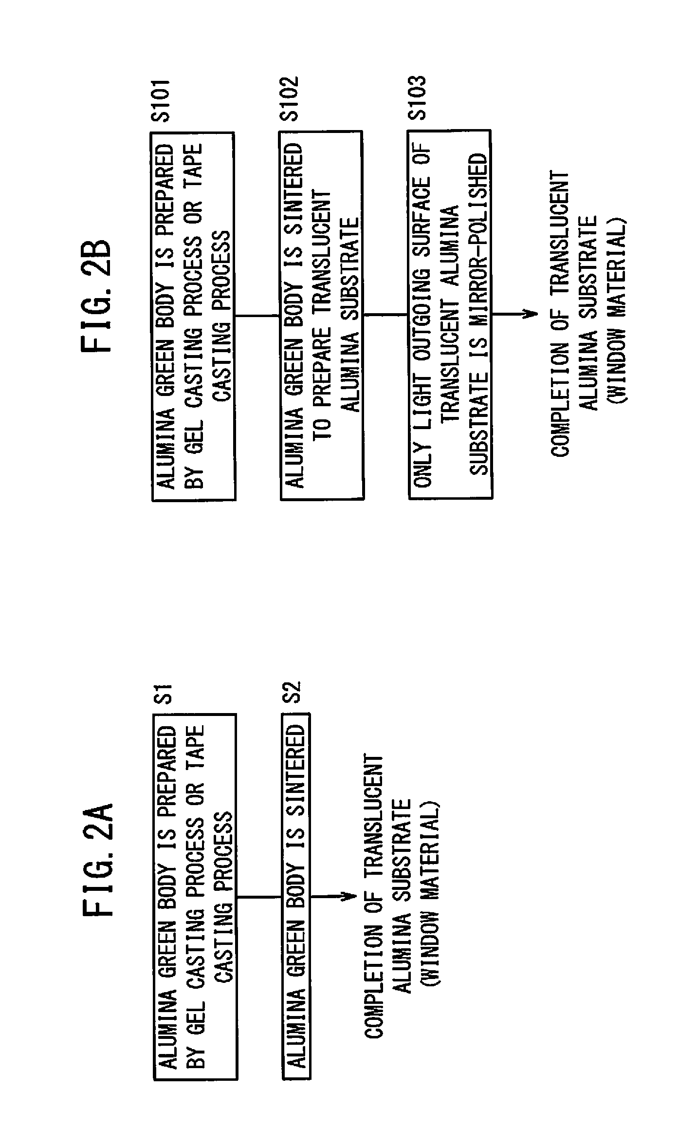
[0076]According to the first production method shown in FIG. 2A, a slurry containing a ceramic powder, a dispersion medium, and a gelling agent was cast into a mold. The slurry was converted to a gel to prepare an alumina green body, and the alumina green body was sintered to obtain a translucent alumina substrate 14 of Example 1.

[0077]Specifically, 500 ppm of a magnesium oxide powder was added to a high-purity alumina powder having a purity of 99.99% or more, a BET surface area of 9 to 15 m2 / g, and a tap density of 0.9 to 1.0 g / cm2. The starting material powder was formed by a gel casting process. 100 parts by weight of this powder, 40 parts by weight of a dispersion medium (dimethyl malonate), 8 parts by weight of a gelling agent (modified 4,4′-diphenylmethane diisocyanate), 0.1 to 0.3 parts by weight of a reaction catalyst (triethylamine), and a nonionic dispersing agent were mixed.

[0078]The slurry was prepared at 20° C. by the steps of dispersing the starting material powder and...

example 2

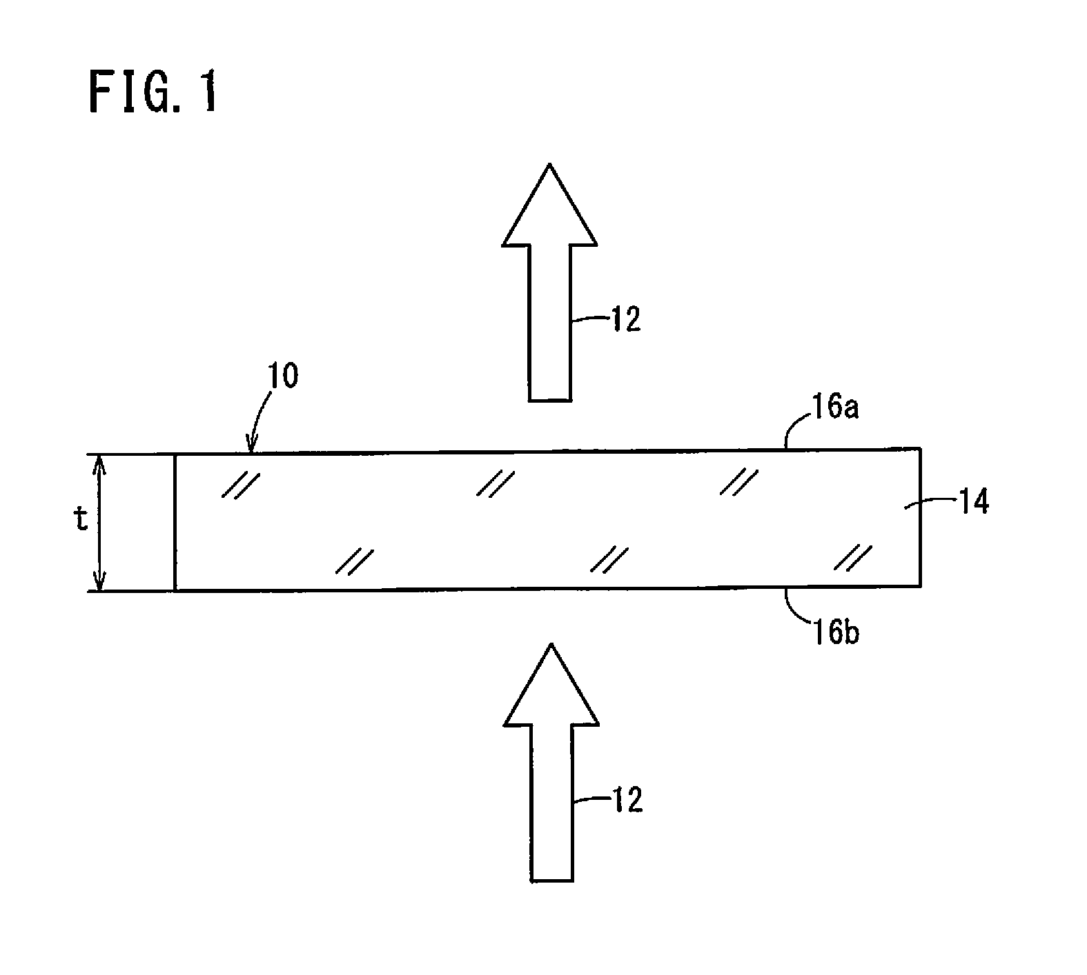
[0081]A translucent alumina substrate 14 of Example 2 was produced in the same manner as Example 1 except that the average grain diameter of the alumina powder (or the sintering temperature or the sintering time) was changed. The translucent alumina substrate 14 had a thickness t of 0.3 mm and had a surface with an average grain diameter of 12 μm. Both of the light outgoing surface 16a and the light entering surface 16b had the same surface roughness Ra of 0.2 μm. The front total light transmittance of the translucent alumina substrate 14 was measured. As a result, the translucent alumina substrate 14 exhibited an average transmittance of 90% in the wavelength region of 200 to 280 nm, and exhibited a transmittance of 95% at a wavelength of 210 nm.

example 3

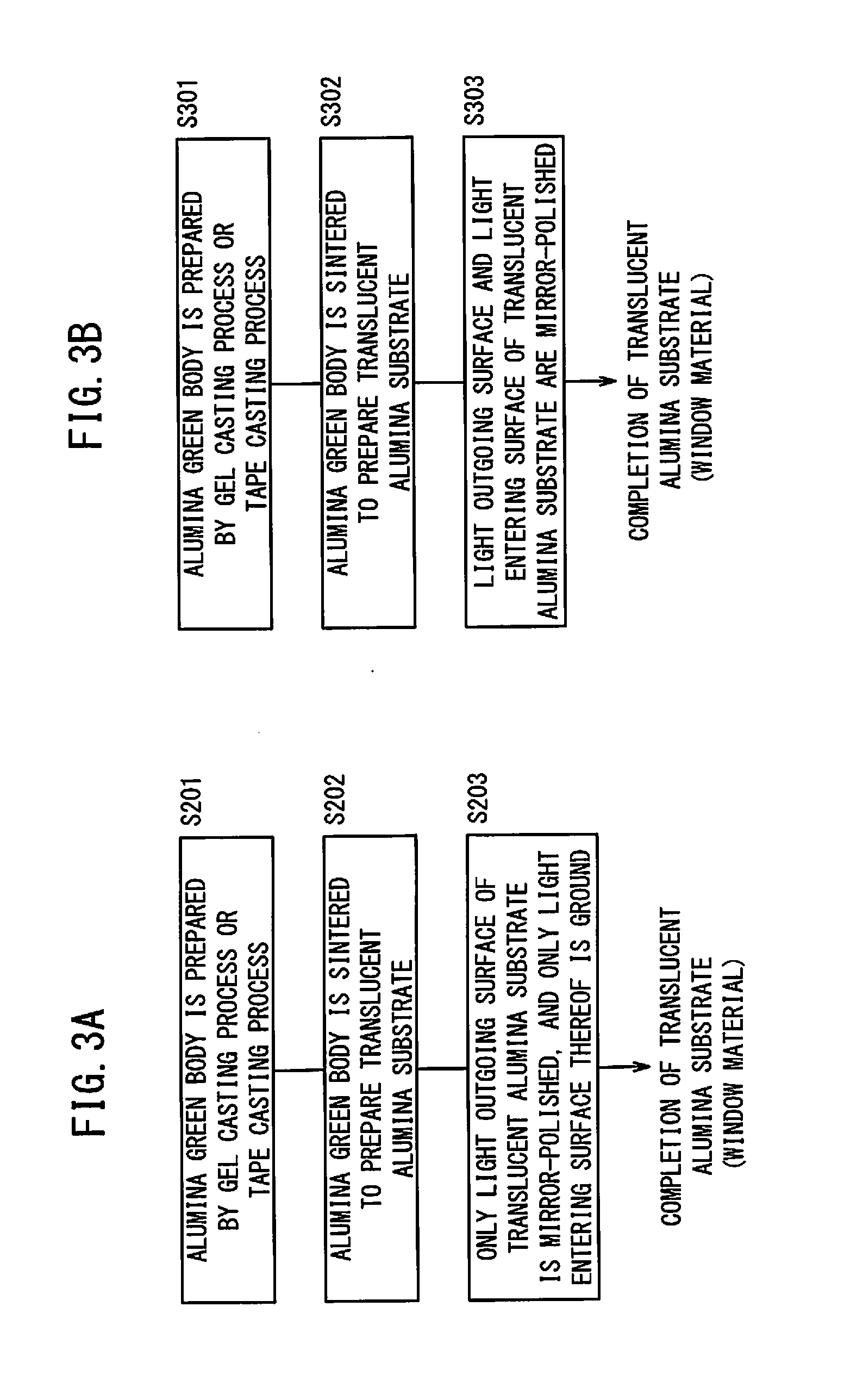
[0082]According to the second production method shown in FIG. 2B, a translucent alumina substrate 14 of Example 3 was produced. First, a translucent alumina substrate 14 having a thickness of 0.5 mm was prepared in the same manner as Example 1. Then, only the light outgoing surface 16a of the translucent alumina substrate 14 was mirror-polished to produce the translucent alumina substrate 14 of Example 3 having a thickness of 0.3 mm. Before the mirror polishing, the surface of the translucent alumina substrate 14 had an average grain diameter of 20 μm, and both of the light outgoing surface 16a and the light entering surface 16b had the same surface roughness Ra of 0.3 μm. After the mirror polishing, the light outgoing surface 16a of the translucent alumina substrate 14 had a surface roughness Ra of 0.03 μm. The front total light transmittance of the translucent alumina substrate 14 was measured. As a result, the translucent alumina substrate 14 exhibited an average transmittance of...


PUM

PropertyMeasurementUnit
wavelengthaaaaaaaaaa
grain diameteraaaaaaaaaa
surface roughnessaaaaaaaaaa

Abstract

A window material for an ultraviolet light emitting device for emitting an ultraviolet light having a wavelength of 300 nm or less is mounted on at least an ultraviolet light emitting side of the ultraviolet light emitting device. The window material for an ultraviolet light emitting device contains a translucent alumina substrate, and a surface of the window material has an average grain diameter of 6 to 60 μm.

Description

CROSS-REFERENCE TO RELATED APPLICATIONS[0001]This application is a Continuation of International Application No. PCT / JP2014 / 065317 filed on Jun. 10, 2014, which is based upon and claims the benefit of priority from Japanese Patent Application No. 2013-123466 filed on Jun. 12, 2013, the contents all of which are incorporated herein by reference.BACKGROUND OF THE INVENTION[0002]1. Field of the Invention[0003]The present invention relates to a window material for an ultraviolet light emitting device (ultraviolet-ray-emitting element) and a method for producing the same, the window material having an excellent transmittance of an ultraviolet light from an ultraviolet light emitting device for emitting an ultraviolet light having a wavelength of 300 nm or less, such as a light emitting diode, a laser diode, a discharge lamp, or the like.[0004]2. Description of the Related Art[0005]Ultraviolet lights have been used for various purposes depending on the wavelengths. Particularly, an ultrav...

Claims


Application Information

Patent Timeline
Patent Type & Authority Applications(United States)
IPC IPC(8): C04B35/115G02B1/12B29B11/14
CPCC04B35/115B29B11/14G02B1/12B29L2011/00C04B2235/6025C04B2235/786B29K2505/02C04B2235/6023G02B5/0242G02B5/0278C04B35/62655C04B35/634C04B35/638C04B2235/5409C04B2235/72C04B2235/95C04B2235/963B29C49/071B29C2949/0715
Inventor NOMURA, MASARUOHASHI, TSUNEAKIMIYAZAWA, SUGIO
Owner NGK INSULATORS LTD
Why Eureka
Try Eureka