Phosphate photonic crystal fiber and converter for efficient blue generation

a technology of phosphate photonic crystal fiber and converter, which is applied in the field of fiber lasers, can solve the problems of difficult power scaling in the 9xx nm (i.e., 900-999 nm) region, aperture restricting the fiber from bending, etc., and achieves short wavelength of operation, effective reduction of gain, and favorable gain characteristics

Active Publication Date: 2016-04-07
BAE SYST INFORMATION & ELECTRONICS SYST INTERGRATION INC
View PDF10 Cites 5 Cited by
  • Summary
  • Abstract
  • Description
  • Claims
  • Application Information

AI Technical Summary

Benefits of technology

[0006]In a preferred embodiment, the invention may use a photonic crystal fiber (PCF) structure as a wavelength filter. In addition to the use of the PCF as a wavelength filter, the large mode area of PCF fibers (i.e., large core diameter, small numerical aperture) allows for favorable gain characteristics for short wavelength of operation, effectively reducing the gain at longer wavelengths. This allows for propagation of the 975 nm light in the fiber core, while leaking any 1030 nm light into the cladding, thereby effectively reducing the overlap of the 1030 nm light with the Yb doping and reducing the gain. In addition, the present invention may use, for example, a phosphate glass as the host material for propagation of the 975 nm light. The inventors discovered that phosphate glass has more favorable gain properties, at 975 nm, than compared to silica glass where the emission and absorption cross section are nearly identical. In phosphate glass, the cross sections provide high emission, with lower absorption, thereby enabling efficient lasing at 975 nm, with low laser threshold. In the silica glass, the absorption and emission cross sections are identical, meaning that this is a highly three-level transition with a high threshold. With phosphate glass, on the other hand, the emission cross section is almost two times higher than the absorption cross section. This is still a three-level transition, but the discrepancy between the emission and absorption means that the overall gain is higher, thereby allowing for better optical performance at 975 nm.
[0007]The present invention addresses several methods for enhancing the gain at the short wavelength transition, while simultaneously suppressing gain at the 1-micron transitions, thereby allowing for highly efficient operation in the 900-980 nm region. This also allows for power scaling in the 9XX nm (i.e., 900-999 nm) region which, using conventional approaches, has be difficult. The system may use a photonic crystal fiber structure for dispersion engineering and efficiency. This allows for good overlap of the 9XX nm transition with the doped fiber core while, at the same time, suppressing the gain in the 1-micron transition through modal leakage. The PFC structure and the material dispersion may be chosen to allow for single-moded beam propagation in the fiber core, at 975 nm (for a Yb-doped fiber), while suppressing modal confinement in the core for 1030 nm light. This lack of confinement causes the 1030 nm light to leak into the exterior cladding, thereby effectively reducing the gain that any spontaneously generated 1030 nm photon can achieve. The use of a photonic crystal fiber structure allows for very high efficiency due to pump and signal overlap. The PCF structure allows the present invention to achieve a very large core diameter (>100 microns) with a low numerical aperture (NA<0.03). This provides a large mode field with a single-mode beam propagation. The large core diameter allows for high energy scaling and higher nonlinear thresholds, compared to standard step index fibers. However, the low numerical aperture restricts the fiber from bending. The present invention uses this to its advantage to have a bend-loss-induced mode filtering at 1030 nm, further reducing gain at 1030 nm.
[0008]The photonic crystal fiber may be a phosphate glass, or some other silicate based glass having a high solubility of rare earth elements. This enables a short gain length to be used (less than 0.25 m in length, for example). The short gain length minimizes losses. The high doping, that can be achieved in phosphate glasses, allows for better pump absorption properties. This is important due to bleaching effects of the resonant pumping. The high doping and the short gain length are important for pulsed lasers, as this increases the nonlinear thresholds in the fiber core, allowing for higher energy and peak-power scaling compared to traditional silica-based fiber rods which can be >1 m in length. Phosphate and silicate glass have inherently higher nonlinear thresholds, further improving peak power scaling. As a result, only a single nonlinear conversion mechanism or stage is required to achieve the blue output having a wavelength of 488 nm, for example. Since the PCF structure can generate 975 nm light directly, only a single second harmonic generator (SHG) mechanism is needed to obtain the desired blue portion of the spectrum. The use of single second harmonic generator mechanism means that the efficiency loss, due to the second harmonic generator, are minimized and this thereby increasing the overall efficiency of the system. According to the present invention, second harmonic generator efficiencies of greater than 50% can be achieved.
[0009]By using a phosphate glass photonic crystal fiber rod as a gain medium, it is possible to suppress the Yb gain at 1030 nm and force lasing / amplification at the ˜975 nm peak. The frequency doubling of the 975 nm transition allows for a blue light output with greater than 10% electrical-to-optical efficiency, which is almost an order of magnitude more efficient than currently available approaches. By using a phosphate glass (or silicate glass), along with a PFC structure, it is possible to enhance the gain of the laser medium at 975 nm. In addition, using phosphate glass, in a photonic crystal waveguide structure, makes it possible to engineer the dispersion in the waveguide. Such dispersion allows for excellent propagation of the waveguide, particularly at 975+15 nm, within the core of the waveguide structure, but does not allow for 1-micron light to propagate in the core. This means that the waveguide modes are lossy at 1030 nm, thus suppressing its overlap with the doped region, and decreasing the gain, allowing for efficient extraction of 975 nm wavelength (power), rather than 1030 nm wavelength (power). This, in turn, eliminates parasitic losses and can allow for high output power and energy at 975 nm. This 975 nm output can then be doubled, and its wavelength halved, in order to generate the desired blue light, e.g., having a wavelength of 487.5 nm, for example. Due to the waveguide nature of the glass structure as well as the gain filtering, the present invention can achieve greater than 50% optical efficiency with the 975 nm light and greater than 50% efficiency conversion into the desired blue light, thereby significantly improving the overall efficiency of this blue laser in comparison to conventional approaches known in the art.

Problems solved by technology

This also allows for power scaling in the 9XX nm (i.e., 900-999 nm) region which, using conventional approaches, has be difficult.
However, the low numerical aperture restricts the fiber from bending.

Method used


Image

  • Phosphate photonic crystal fiber and converter for efficient blue generation
  • Phosphate photonic crystal fiber and converter for efficient blue generation
  • Phosphate photonic crystal fiber and converter for efficient blue generation

Examples


second embodiment

[0042]Turning now to FIG. 4, the present invention will now be described. As this embodiment is very similar to the previously discussed embodiment, only the differences between this new embodiment and the previous embodiment will be discussed in detail while identical elements will be given identical reference numerals.

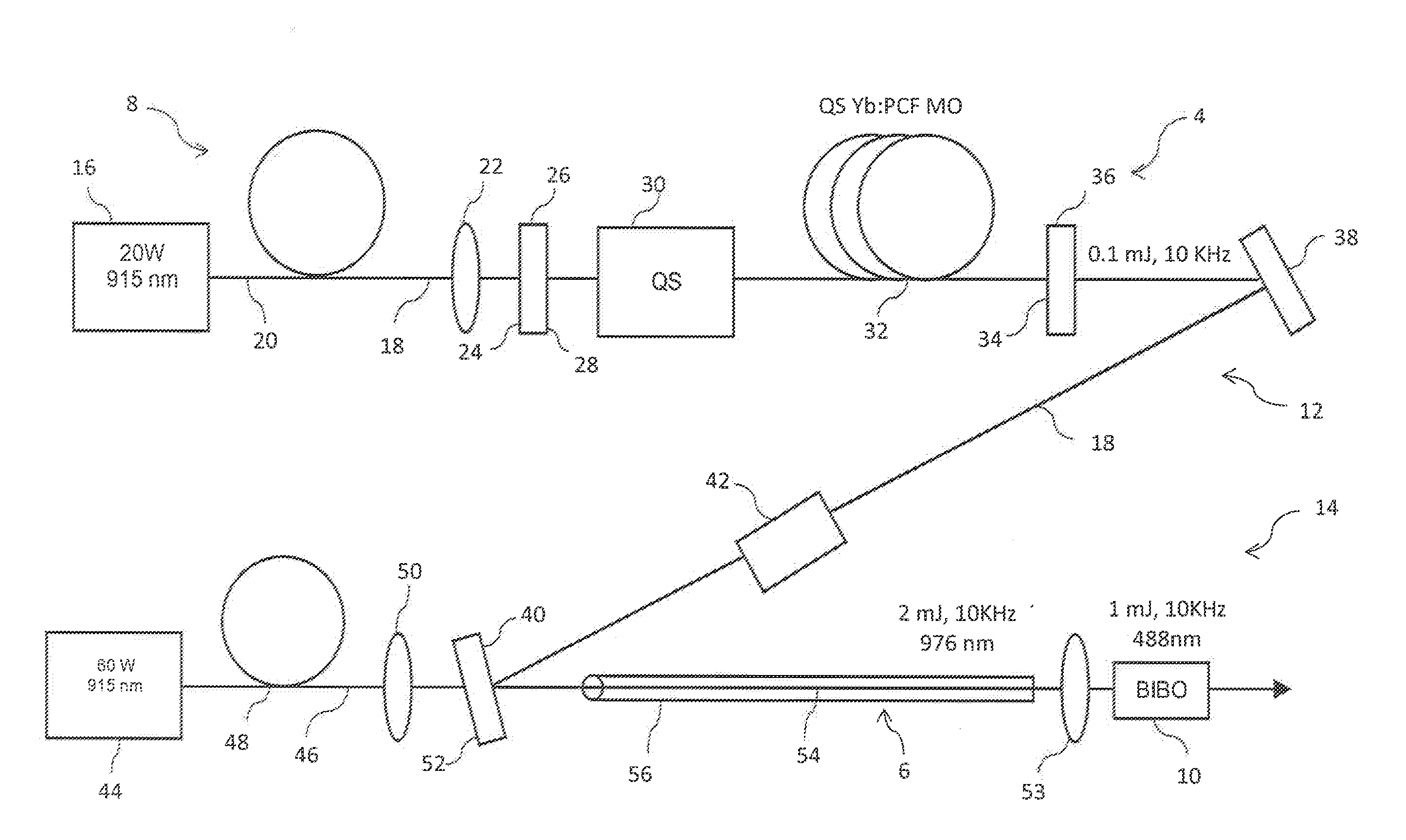
[0043]FIG. 4 shows a simplified embodiment of a phosphate photonic crystal fiber (PPCF) amplifier 6 with a single nonlinear converter 10 and generally includes a pump source 44, a seed source 18′ (supplied by a first source—not shown), the PPCF amplifier 6, and the nonlinear converter 10. According to this embodiment, the laser seed beam 18′, generated by the first source and having a wavelength of 975 nm, propagates toward and is reflected by a first surface 63 of a seed mirror 64 toward the amplifier 6.

[0044]The second (laser) pump source 44, according to this embodiment, pumps 900-950 nm light into the system 8. The second pump beam 46, from the pump source 44 and...

third embodiment

[0047]Turning now to FIG. 5, the present invention will now be described which is similar to the previously discussed embodiment. In FIG. 5, a simplified embodiment of a phosphate photonic crystal fiber (PPCF) laser oscillator 76, operating as a continuous wave (CW) with single nonlinear converter 10, is shown. According to this embodiment, the pump source 72 generates a laser first (laser) pump beam 74, having a wavelength of 900-950 nm, and propagates the first (laser) pump beam 74 toward a first end of a focusing lens assembly (typically comprising a plurality of lens) 61. A second opposite end of the focusing lens assembly 61 is aligned to propagate the first pump beam 74 toward a first surface 24 of the high reflector 26 which permits substantially all of supplied first pump beam 74 to pass therethrough and enter into the PPCF laser oscillator 76. An opposed second surface 28 of the high reflector 26, is coated with a coating which reflects substantially 100% of the 976 nm back...


PUM


Abstract

In the method for generating blue laser light with high optical and electrical efficiency, wherein the improvement comprises the step of using a phosphate glass photonic crystal fiber rod as a gain medium.

Description

[0001]This application claims priority from U.S. Provisional Application Ser. No. 62 / 060,876 filed Oct. 7, 2014.FIELD OF THE INVENTION[0002]This invention relates to lasers, and more particularly, to fiber lasers.BACKGROUND OF THE INVENTION[0003]Typical blue lasers require cascaded nonlinear conversion, which decreases efficiency. They can also employ a single nonlinear mechanism or stage when operating on a short wavelength of Neodymium (Nd) to Ytterbium (Yb). However, suppression of the gain peaks, in the 1-micron spectral region, is difficult and generally requires optical filtering techniques, which limits the overall power and energy which can be achieved. Operating Yb at 975 nm, similar to operating a Nd-doped laser at 911 nm, suffers from parasitic lasing effects and amplified spontaneous emission (ASE) due to the high gain at the 1030 nm and 1064 nm gain peaks, respectively. In order to operate on the shorter wavelength transitions, the losses in the 1-micron region must be ...

Claims


Application Information

Patent Timeline
Patent Type & Authority Applications(United States)
IPC IPC(8): H01S3/094H01S3/067H01S3/00
CPCH01S3/094003H01S3/06754H01S3/06741H01S3/0092H01S3/06716H01S3/094007H01S3/1611H01S3/1618
Inventor CREEDEN, DANIEL J.KETTERIDGE, PETER A.MOFFITT, PAUL R.SNELL, KATHERINE J.
Owner BAE SYST INFORMATION & ELECTRONICS SYST INTERGRATION INC
Why Eureka
Try Eureka