
Method and plant for redox chemical looping combustion of a solid hydrocarbon feedstock

a technology of hydrocarbon feedstock and combustion method, which is applied in the direction of combustion types, furnaces, lighting and heating apparatuses, etc., can solve the problems of sticking of solid fuel injected into the clc, fouling of the clc plant, and obstruction of the injector, so as to improve the dispersion of redox active mass particles

Active Publication Date: 2016-05-26
TOTALENERGIES ONETECH +2
View PDF8 Cites 4 Cited by
  • Summary
  • Abstract
  • Description
  • Claims
  • Application Information

AI Technical Summary

Benefits of technology

This patent describes a method and plant for a CLC process that can reduce the problems of fouling and sticking in the plant, and also help to dispose of unwanted material. The method involves using injection means to improve the dispersion of redox active mass particles and agglomerated bottom ash in the separation zone. This will help to achieve better purification and reduce the loss of redox active mass during the process. Overall, this patent provides a solution for improving the efficiency and reliability of the CLC process.

Problems solved by technology

The combustion of solid hydrocarbon feeds such as coal causes CLC plant fouling problems.
One major problem likely to arise upon the combustion of solid hydrocarbon feeds lies in the sticking of the solid fuel injected into the CLC plant, notably at the injector allowing the feed to be sent into the combustion reactor.
In the case of gravity injection of coal into a fluidized bed for example, the significant heat generated in the injector, by conduction with the high-temperature bed of the combustion reactor, can lead to sticking of the crushed coal and cause an obstruction in the injector.
Another problem relates to the formation of ashes in the combustion reaction zone, and more particularly the formation of agglomerated bottom ash whose agglomeration may “foul” the reactor.
This phenomenon affects the smooth operation of the CLC process and it may require complete stoppage of the plant for maintenance.
The grain size of the agglomerated ashes is more delicate to estimate and depends on the conditions of implementation of the method.
However, these devices work only for the fines produced by attrition of the oxygen-carrying material (through chemical or mechanical aging effect), the unburned solid fuel particles (“unburned particles”) and the fly ashes.
Although these simple means provide a solution to the agglomerated bottom ash problem, they are by no means selective, and a larger proportion of oxygen carrier (predominant in the fluidized bed) than ashes proper will eventually be extracted.
However, this device does not enable satisfactory extraction of the agglomerated bottom ash, which represents a small proportion of the particle stream withdrawn.
Non-selective or weakly selective extraction of agglomerated bottom ash can in the long term affect the process performances and increase the operating costs.

Method used


Image

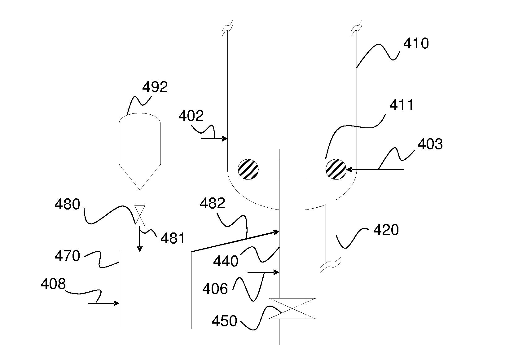
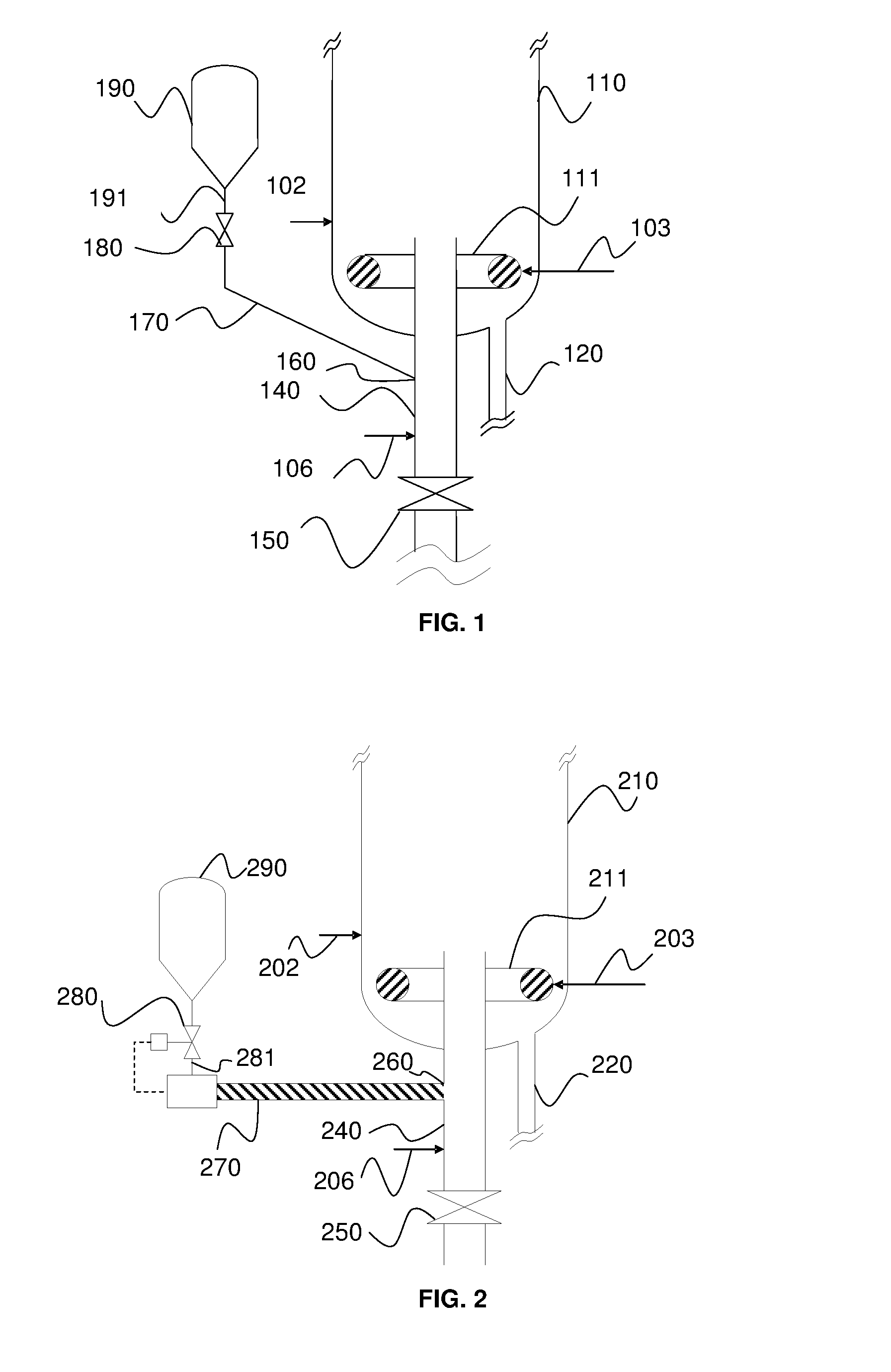
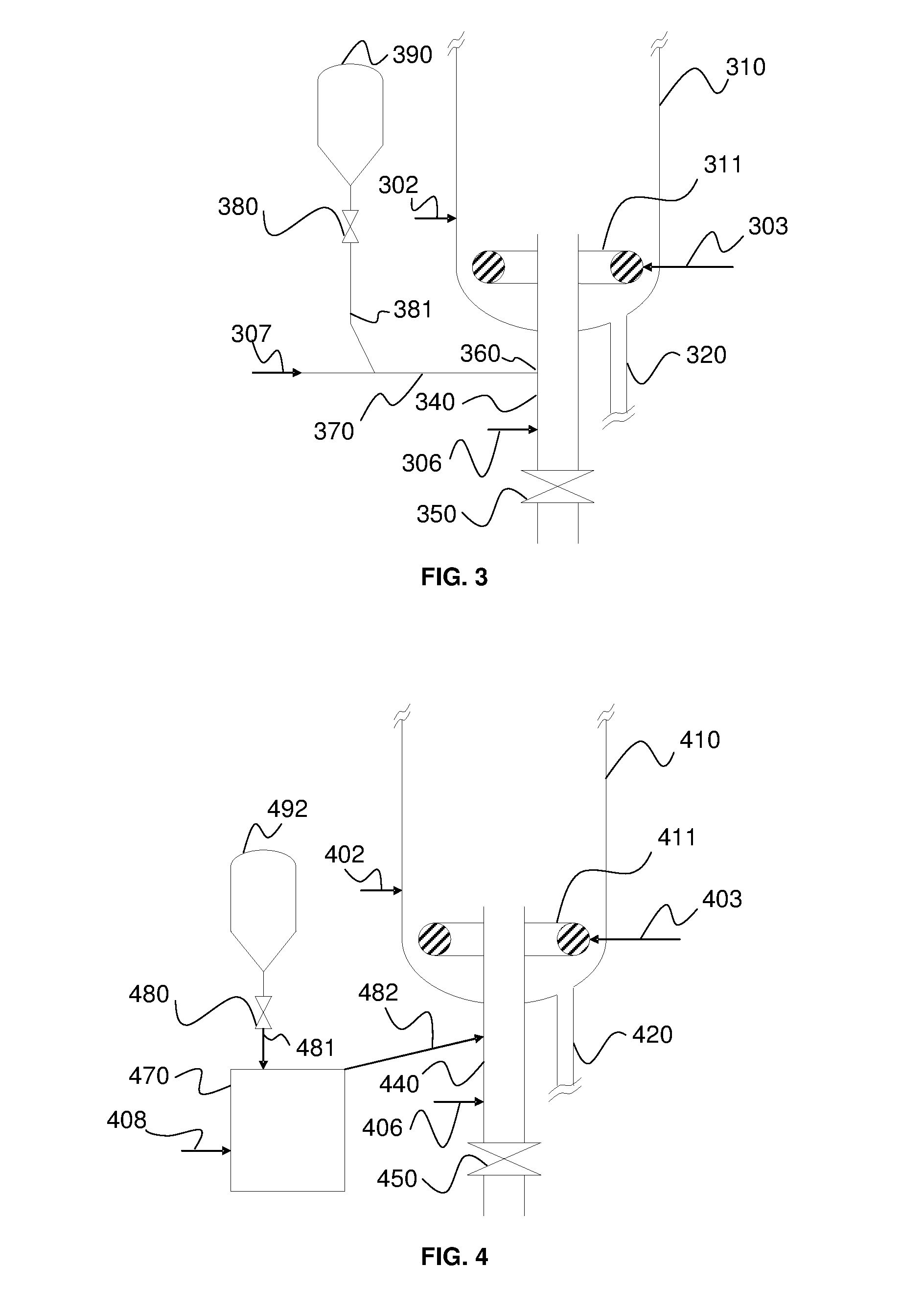
  • Method and plant for redox chemical looping combustion of a solid hydrocarbon feedstock
  • Method and plant for redox chemical looping combustion of a solid hydrocarbon feedstock
  • Method and plant for redox chemical looping combustion of a solid hydrocarbon feedstock

Examples


example 1

[0165]This example relates to the configuration described in connection with FIG. 5.

[0166]The fluidized bed of combustion reactor 510 is a 2-MWth coal combustion fluidized bed. It is supplied with 0.078 kg / s of South African coal whose characteristics are given in Table 2 hereafter.

TABLE 2Composition and characteristics of the carbon feedCWt. %70.00HWt. %4.14OWt. %9.32NWt. %1.84SWt. %0.80AshesWt. %13.90Volatile matter %%29.90Fixed carbon %%56.20Humidity %%4.00Ultimate drying LHVkJ / kg26.843Air drying LHVkJ / kg25.769Raw coal flowkg / s0.078

[0167]The combustion reactor is operated in CLC mode at 950° C. under fluidized bed conditions. The fluidized bed is supplied with 5.11 kg / s of redox active mass through supply means 502. The bed is fluidized by 0.04 Nm3 / s water vapour 503.

[0168]A mixture comprising agglomerated bottom ash and active mass particles is extracted from reactor 510 through extraction line 520 at a flow rate of 0.5 kg / s. The solid extracted from the reactor bottom has a hig...

example 2

[0176]Example 2 is a comparative example corresponding to an implementation of the CLC method according to the prior art. We consider in this example the same configuration as in Example 1 as regards equipments 510, 503, 530. However, in this example, there is no elimination of the ashes according to the invention and extraction line 520 does not open onto a separation zone, but directly onto the outside.

[0177]The solid mixture extracted from the unit at a rate of 0.5 kg / s has a composition of 20% agglomerated bottom ash as defined in Example 1 and 80% redox active mass as defined in Example 1.

[0178]Table 3 gives the data relative to the streams extracted from line 520 and from the CLC unit (bottom of 140) for Examples 1 and 2.

TABLE 3Input / output comparative of Examples 1 and 2Ex1Ex2Ex1Ex2(120)(120)(bottom of 140)(bottom of 140)Flow (kg / s)0.50.50.1200.5Agglomerated20208320bottom ash %Active mass %80801780

[0179]The redox active mass outputs need to be compensated by a makeup supply s...


PUM


Abstract

The invention relates to a method and to a device for chemical looping combustion CLC of a solid hydrocarbon feed wherein it is proposed to inject the solid hydrocarbon feed so as to limit any occurrence of sticking of the feed to the walls of the injection device. The solid feed is fed into a conveying zone operating under fluidized bed conditions and opening into a combustion reactor. A fluidization gas is injected into this conveying zone while controlling the flow of gas in such a way that the superficial velocity of the gas in the conveying zone is higher than the terminal velocity of the solid hydrocarbon feed particles and the terminal velocity of solid particles present in the combustion reactor, and while controlling the fluidization gas temperature in such a way that the temperature in the conveying zone is less than or equal to 500° C.

Description

FIELD OF THE INVENTION[0001]The present invention relates to the field of redox chemical looping combustion (CLC) of hydrocarbon feeds under fluidized bed conditions, and more specifically to the fluidized-bed chemical looping combustion of solid hydrocarbon feeds.BACKGROUND OF THE INVENTION[0002]In the text hereafter, what is referred to as CLC (Chemical Looping Combustion) is an oxidation-reduction or redox looping method on an active mass. It can be noted that, in general, the terms oxidation and reduction are used in connection with the respectively oxidized or reduced state of the active mass. The oxidation reactor, also referred to as air reactor, is the reactor where the redox mass is oxidized and the reduction reactor, also referred to as combustion reactor or fuel reactor, is the reactor where the redox mass is reduced.[0003]The CLC method allows to produce energy from hydrocarbon-containing fuels while facilitating capture of the carbon dioxide emitted during combustion.[0...

Claims


Application Information

Patent Timeline
Patent Type & Authority Applications(United States)
IPC IPC(8): F23C10/01F23C10/00F23C10/28F23C10/20F23C10/22F23D1/00F23C10/04
CPCF23C10/01F23D1/00F23C10/002F23C10/28F23C10/20F23C10/22F23C10/04F23C10/005F23C10/26F23C2900/99008Y02E20/34
Inventor GUILLOU, FLORENTSOZINHO, TIAGODREUX, HELOISESTAINTON, HELENE
Owner TOTALENERGIES ONETECH
Learn More