Coupled Inductor for Interleaved Multi-Phase Three-Level DC-DC Converters

a technology of inductor current and interleaved, which is applied in the direction of dc-dc conversion, power conversion systems, instruments, etc., can solve the problems of large input and output capacitances, large parallel connection, and large circulating current ripple in the inductor current, so as to reduce output current ripple and reduce current circulating

Active Publication Date: 2016-06-16
VIRGINIA TECH INTPROP INC
View PDF5 Cites 35 Cited by
  • Summary
  • Abstract
  • Description
  • Claims
  • Application Information

AI Technical Summary

Benefits of technology

[0014]In accordance with a further aspect of the invention, a method of reducing output current ripple in a three-level DC-DC power converter is provided comprising steps of connecting at least two of phase legs in parallel, each said phase leg including an inductor, conducting power from a power source through each of the at least two phase legs in an interleaved manner, and generating a voltage that reduces current circulating in the at least two phase legs due to interleaving of the conducting of power in the phase legs in an interleaved manner.

Problems solved by technology

However, doing so results in a substantial output ripple voltage and input and output ripple current, requiring large input and output capacitances.
However, when the legs of a multi-phase, three-level power converter are operated in an interleaved manner for output current ripple and output capacitor size reduction, the parallel connection allows an abnormally large circulating current ripple in the inductor current which is larger than the output current ripple.
This circulating ripple current is a source of resistive losses in the inductors and other circuitry, increased turn-off switching losses and requires a larger inductor to maintain a given level of input and output ripple.
Therefore, use of interleaved operation of a power converter to reduce input and output ripple has compromised both efficiency and power density as well as cost and weight.
A three-level power converter, whether or not operated in an interleaved manner, may also cause common mode (CM) noise to be developed at the switching frequency, requiring attenuation by a filtering arrangement to prevent CM noise from being reflected back to the power source.
Interleaved operation will reduce the CM noise somewhat but causes high circulating current which is not tolerable for practical use.
Since the frequency of the CM noise is at the switching frequency which is relatively low to limit switching losses, the CM filter required for attenuation at the switching frequency is therefore usually relatively large and a significant fraction of the total volume of the power converter, which, in turn, tends to limit the power density of the power converter design.
Thus, in high power applications, passive components are a major factor affecting power converter system costs, volume and weight while input and output ripple specifications are becoming more stringent in some applications such as photovoltaic (PV) cell arrays for solar power generation where ripple causes deleterious effects on the PV cells.

Method used


Image

  • Coupled Inductor for Interleaved Multi-Phase Three-Level DC-DC Converters
  • Coupled Inductor for Interleaved Multi-Phase Three-Level DC-DC Converters
  • Coupled Inductor for Interleaved Multi-Phase Three-Level DC-DC Converters

Examples


Embodiment Construction

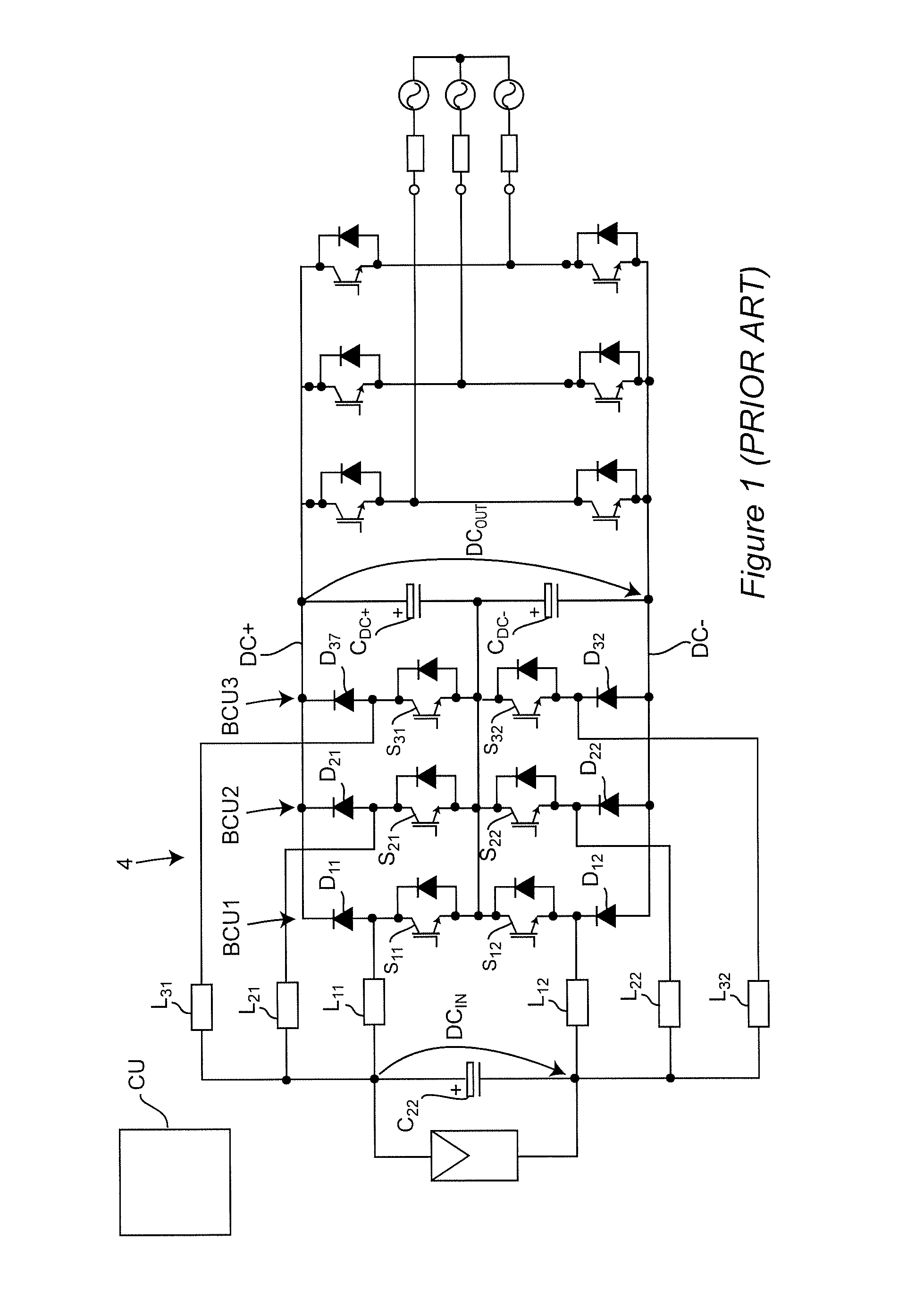
[0063]Referring now to the drawings, and more particularly to FIG. 1, there is shown a generalized schematic diagram of an interleaved three-level converter (iTLC) having three phase three-level converter (TLC) legs or buck / boost converter units (BCUs) that has been proposed for PV applications in order to reduce input and output current ripple. As alluded to above, high frequency current ripple is particularly undesirable in regard to solar power collectors and causes premature aging and failure of PV cells in the solar collector PV array(s). In this power converter circuit topology, the input and output current ripple will be greatly reduced and the size or value of input and output capacitors can be greatly reduced to meet current ripple specifications due to the cancellation effect of interleaving as shown in the following Table I. The angular references are to the leading edge of on-time of the switches indicated.

TABLE IBCU1BCU2BCU3S110S212π / 3 (120°)S314π / 3 (240°)S12π / 3 (60°)S2...


PUM


Abstract

Output current ripple is reduced in a three-level DC-DC power converter by connecting a plurality of phase legs in parallel between a source of input power and an output of the power converter and conducting power from the source of input power to the power converter output in an interleaved manner. The large current that results from such interleaved operation is reduced to acceptable levels, potentially less than the output current ripple of the power converter by providing inversely coupled inductors having a mutual inductance preferably greater than the inductor of the power converter in respective phase legs and in series in the circulating current path to avoid any need to increase the power converter inductance due to the circulating current. The inductor and inversely coupled inductors are preferably integrated into a single magnetic element of compact design.

Description

CROSS-REFERENCE TO RELATED APPLICATIONS[0001]This application claims benefit of priority of U.S. Provisional Application 62 / 092,312, filed Dec. 16, 2014, which is hereby incorporated by reference in its entirety.FIELD OF THE INVENTION[0002]The present invention generally relates to switching power converters and switching voltage regulators and, more particularly, to multi-level, multi-phase interleaved switching power converters and switching voltage regulators capable of delivering high current at high voltage and which may be bi-directional and having reduced inductor ripple and overall output current ripple and common mode noise.BACKGROUND OF THE INVENTION[0003]While alternating current (AC) power is used for transferring power from a location where the power is generated to a remote load, many, if not most, loads other than electric motors require power at a direct current (DC), substantially constant voltage. Therefore, many of these potential loads require a dedicated power c...

Claims


Application Information

Patent Timeline
Patent Type & Authority Applications(United States)
IPC IPC(8): H02M3/158H02M1/14
CPCH02M1/14H02M3/158H02M7/487H02M7/493H02M1/123H02M1/0043
Inventor MU, MINGKAILU, SIZHAOJIAO, YANGLEE, FRED C.
Owner VIRGINIA TECH INTPROP INC
Why Eureka
Try Eureka