
Method of manufacturing soft magnetic material

a soft magnetic composite material and manufacturing method technology, applied in the direction of magnetic materials, magnetic bodies, electron beam welding apparatus, etc., can solve the problems of poor electromagnetic conversion rate, iron loss, and the inability of soft magnetic composite materials to achieve mass production or large scale or complex shapes, etc., to achieve low temperature rise rate, low iron loss, and simple manufacturing process

Inactive Publication Date: 2016-06-23
METAL INDS RES & DEV CENT
View PDF0 Cites 4 Cited by
  • Summary
  • Abstract
  • Description
  • Claims
  • Application Information

AI Technical Summary

Benefits of technology

The present invention provides a method of manufacturing soft magnetic material with one-step forming and excellent magnetic properties, which can reduce energy loss caused by electromagnetic conversion process. The manufacturing process is simpler than that of silicon steel sheet and the soft magnetic material has low temperature rising rate (low iron loss), high magnetic permeability, and good electromagnetic shielding properties. This material can be used as the iron core of electronic products and make them more stable in operation and not affected by electromagnetic effect. The additive manufacturing device can control the beam power and the beam melting time, which can adjust the cooling and condensation rate of the working powder. Overall, this method and device have various advantages and can improve electronic products' operation stability and performance.

Problems solved by technology

For example, during usage, the temperature of the silicon steel sheet will easily rise to cause iron loss and poor electromagnetic conversion rate.
However, due to the limitation of the metallic glass forming ability (GFA) and foundry technology, most of the soft magnetic composite materials cannot achieve mass production or form large scale or complex shapes.

Method used


Image

  • Method of manufacturing soft magnetic material
  • Method of manufacturing soft magnetic material
  • Method of manufacturing soft magnetic material

Examples


Embodiment Construction

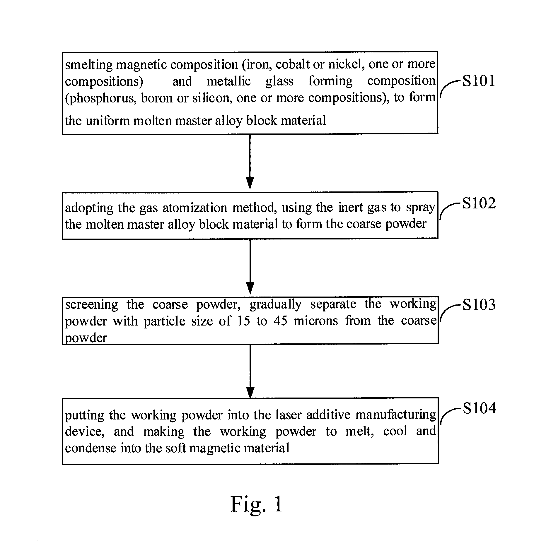
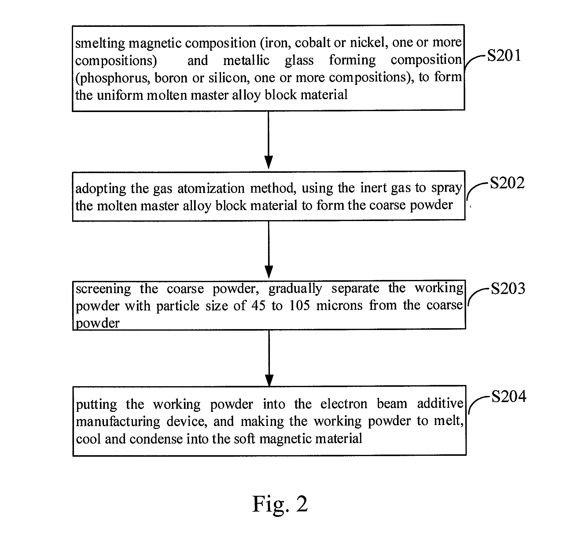
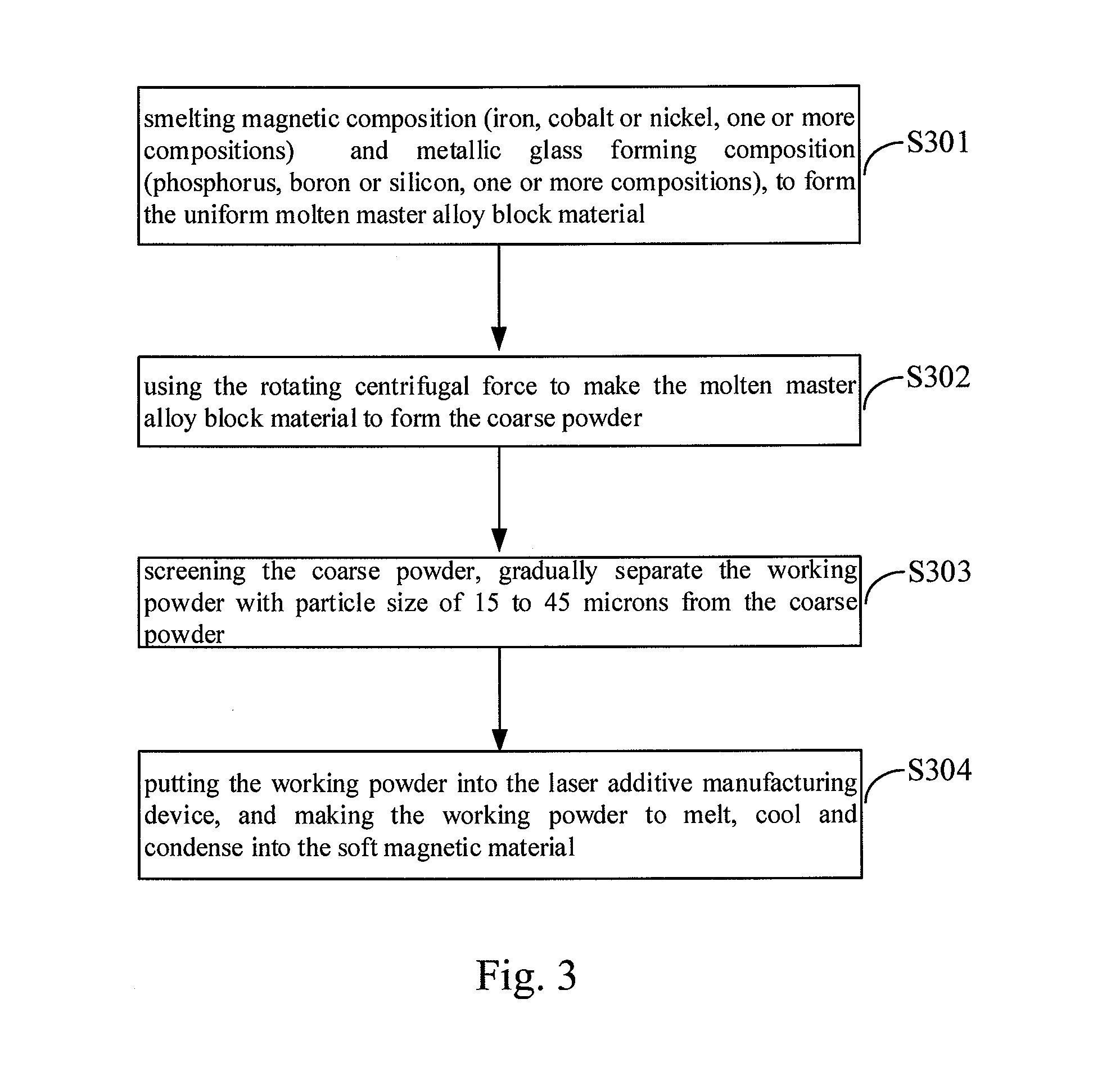
[0024]The present invention provides a method of manufacturing soft magnetic material, which is a kind of amorphous soft magnetic material with one-step forming and can be enough to replace the traditional core material. The method includes smelting magnetic composition and metallic glass forming composition, to form the uniform molten master alloy block material. The magnetic composition is iron, cobalt or nickel. The metallic glass forming composition is phosphorus, boron, molybdenum, niobium, zirconium silicon, or carbon. In particular, the master alloy block material is smelted from iron, cobalt or nickel (one or more compositions) and phosphorus, boron, silicon, carbon, niobium, zirconium or molybdenum (one or more compositions). Therefore, the resulting high iron content can maintain the magnetic flux of the master alloy block material. Adding cobalt, nickel or other magnetic materials can increase the deflection, and adding phosphorus, boron, silicon, carbon, niobium, zirconi...


PUM

PropertyMeasurementUnit
particle sizeaaaaaaaaaa
soft magneticaaaaaaaaaa

Abstract

A method of manufacturing soft magnetic material, including smelting magnetic and metallic glass forming compositions, to form a uniform molten master alloy block material, melting the master alloy material into liquid, and exerting a force on the liquid master alloy block material to make it into coarse powder. The coarse powder is screened to separate the working powder, and the working powder is put into an additive manufacturing device, to make the working powder melt, cool and condense into the soft magnetic material. The soft magnetic material is made by a simple process, with low iron loss rate and better electromagnetic shielding feature and other properties, and can improve magnetic permeability and save energy when applied to the electronic products.

Description

BACKGROUND OF THE INVENTION[0001]1. Field of the Invention[0002]The present invention is a method of manufacturing material, especially soft magnetic material.[0003]2. Brief Description of the Prior Art[0004]With the progress of science and technology and the popularity of nano technology, many kinds of large volume, stationary electronic products have been gradually reduced to portable electronic products, including the internal components of electronic equipments. The core materials, rotors, stators and other components of the electronic products are mostly made of silicon steel sheet. Silicon steel sheet has the advantages of easy processing and low cost, but it needs more processes to meet demand due to its characteristics. For example, during usage, the temperature of the silicon steel sheet will easily rise to cause iron loss and poor electromagnetic conversion rate. As such, the pioneers of the field have developed related soft magnetic composite materials to replace silicon ...

Claims


Application Information

Patent Timeline
Patent Type & Authority Applications(United States)
IPC IPC(8): H01F1/153B22F3/105C22C1/00B23K26/00C22C45/00H01F41/02B23K15/00B23K26/342B22F9/04C22C1/02B22F1/08
CPCH01F1/15341B23K2203/02B22F3/1055C22C1/002C22C1/02C22C45/008H01F1/15308H01F1/15316H01F41/02B23K15/0086B23K15/0093B23K26/342B23K26/0006B33Y10/00B22F9/04C22C1/0433C22C33/0207B22F2998/10Y02P10/25B22F10/28B22F12/53B22F1/08C22C1/11B22F9/10B22F9/082
Inventor KUO, CHE-NANTSAI, DE-CHANGFU, HO-CHUNGLU, YING-CHENGYEH, CHUN-LINTSAI, MENG-HSIU
Owner METAL INDS RES & DEV CENT
Learn More