Hybrid dc-dc converter with llc converter and full-bridge converter

a converter and converter technology, applied in the direction of electric variable regulation, process and machine control, instruments, etc., can solve the problems of increasing fuel price, increasing the size and weight of heat sinks, increasing overall efficiency, etc., and achieves reduced size of output filter inductor, low circulating current, and less components

Active Publication Date: 2016-06-30
KOREA INST OF ENERGY RES
View PDF4 Cites 17 Cited by
  • Summary
  • Abstract
  • Description
  • Claims
  • Application Information

AI Technical Summary

Benefits of technology

[0017]As described above, according to the present invention, the hybrid dc-dc converter has following advantages; wide zero-voltage-switching (ZVS) range, low circulating current, zero-current-switching (ZCS) operation on output rectifiers, and reduced size of output filter inductor. Moreover, the hybrid dc-dc converter has low circulating current even though it uses less components. In addition, the hybrid dc-dc converter may be driven in a phase-shift manner with stationary frequency, which helps the LLC converter to be optimally designed on one point without consideration of a battery charger operation status.

Problems solved by technology

With accelerated global warming, decreasing natural resources, increasing fuel price, and economical issues, vehicles with electric propulsion, such as hybrid electric vehicles (HEVs), plug-in HEVs (PHEVs), battery electric vehicles (BEVs or EVs), and fuel cell electric vehicles, are gradually growing.
In addition, in the PFC stage, a bridgeless design should be carried out because excessive conduction loss is generated due to the forward voltage drop for each of the bridge diodes, particularly at a lower line input voltage, which decreases the overall efficiency and greatly increases the size and weight of heat sink.
In addition, in the case where the output voltage requirement of the battery charger is high, the rectifier diodes in the dc-dc converter could experience a serious voltage oscillation and spike.
Then, lossy snubber circuitry and higher voltage-rated diodes must be required, which cause the increase in power loss, size, and weight.

Method used


Image

  • Hybrid dc-dc converter with llc converter and full-bridge converter
  • Hybrid dc-dc converter with llc converter and full-bridge converter
  • Hybrid dc-dc converter with llc converter and full-bridge converter

Examples


Embodiment Construction

[0025]Hereinafter, exemplary embodiments of the present invention will be described with reference to the accompanying drawings. In the following description, the same elements will be designated by the same reference numerals although they are shown in different drawings. Further, in the following description of the present invention, a detailed description of known functions and configurations incorporated herein will be omitted when it may make the subject matter of the present invention rather unclear.

[0026]In addition, terms, such as first, second, A, B, (a), (b) or the like may be used herein when describing components of the present invention. These terms are merely used to distinguish one structural element from other structural elements, and a property, an order, a sequence and the like of a corresponding structural element are not limited by the term. It should be noted that if it is described in the specification that one component is “connected,”“coupled” or “joined” to ...


PUM


Abstract

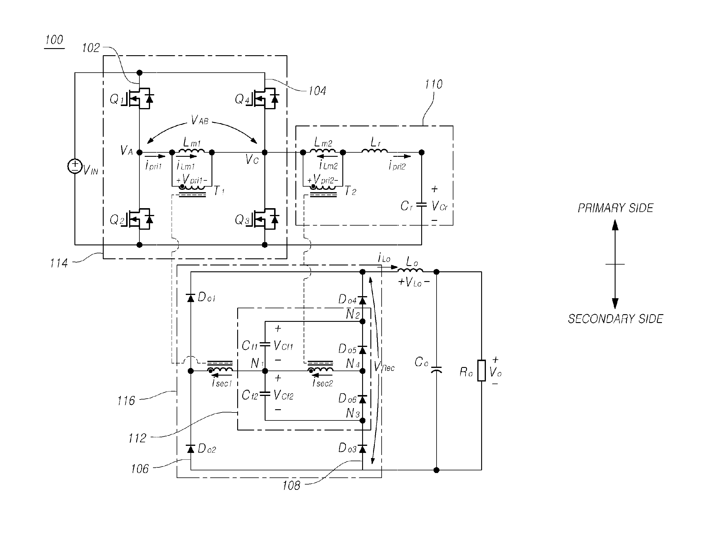
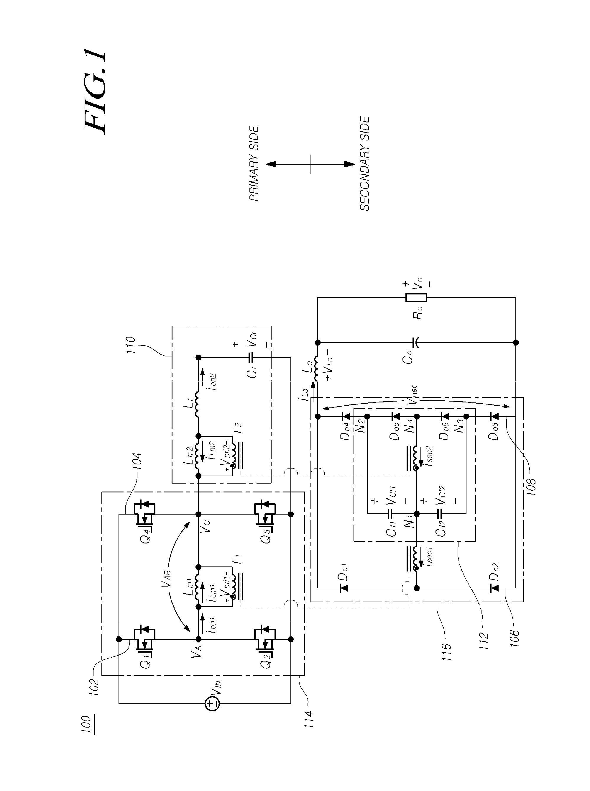
Disclosed is a hybrid dc-dc converter. The hybrid dc-dc converter includes: a pair of transformers configured to magnetically couple a primary side to a secondary side, a full-bridge converter including four switches constituting a full-bridge inverter circuit and a first transformer, and an LLC resonant converter including a resonant inductor, a resonant capacitor, and a second transformer, which constitute an LLC resonant circuit, wherein an output of the full-bridge converter and an output of the LLC resonant converter are connected to each other in series at the secondary side.

Description

BACKGROUND OF THE INVENTION[0001]1. Field of the invention[0002]The present invention relates to a dc-dc converter.[0003]2. Description of the Prior Art[0004]With accelerated global warming, decreasing natural resources, increasing fuel price, and economical issues, vehicles with electric propulsion, such as hybrid electric vehicles (HEVs), plug-in HEVs (PHEVs), battery electric vehicles (BEVs or EVs), and fuel cell electric vehicles, are gradually growing.[0005]These vehicles need commonly rechargeable batteries as the energy source of electric traction system. Among them, PHEVs or EVs require a higher capacity and larger sized battery pack compared with other vehicles because the battery is a main energy source in PHEVs or EVs.[0006]The high-energy-density battery pack in PHEVs or EVs is typically recharged from the ac utility grid via an ac-dc converter named as battery charger. For low harmonic contents on the ac utility grid and high efficiency, most of battery chargers have ge...

Claims


Application Information

Patent Timeline
Patent Type & Authority Applications(United States)
IPC IPC(8): H02M3/335
CPCH02M3/33507H02M3/3378Y02B70/10H02M1/0077H02M1/0058H02M1/0095
Inventor LEE, ILOUNCHAE, SUYONGSONG, YUJINOH, SEASHUNGPARK, SUKINSUNG, YOONDONG
Owner KOREA INST OF ENERGY RES
Why Eureka
Try Eureka