Rotor blade element for a wind turbine, rotor blade, and a production process therefor and wind turbine with rotor blade

a technology of rotor blade and wind turbine, which is applied in the direction of machines/engines, other domestic articles, and final product manufacture. it can solve the problems of poor bonding of uhmwpe with conventional adhesives, and the inability of epoxy resins to direct bond to polyethylene, etc., to achieve excellent heat resistance, excellent flexibility, and good suitability for bonding

Active Publication Date: 2016-07-21
WOBBEN PROPERTIES GMBH
View PDF1 Cites 9 Cited by
  • Summary
  • Abstract
  • Description
  • Claims
  • Application Information

AI Technical Summary

Benefits of technology

[0011]The invention is based on the discovery that the use of surface foils comprising UHMWPE can markedly improve the abrasion resistance of rotor blade elements. The invention moreover includes the discovery that by way of a bonding layer comprising two rubber layers it is advantageously possible to achieve the application and long-lasting bonding of UHMWPE on a base of a rotor blade element made of fiber material and made of curable resin, in particular epoxy resin. UHMWPE features very good resistance to wear and to abrasion even when exposed to abrasive media, its abrasion resistance being six times higher than that of polyurethane. UHMWPE also has excellent chemical stability, and a low coefficient of friction, exceptional dimensional stability, and high impact resistance even at low temperatures. Because of these properties, UHMWPE is of particular interest for use as surface foil for protection from erosion, but bonding of UHMWPE with conventional adhesives gives very poor results. In particular, epoxy resins are not suitable for direct bonding to polyethylene, in particular UHMWPE. However, the invention is based on the discovery that it is possible, by using a bonding layer made of two rubber layers, to achieve application of UHMWPE foils even on rotor blade elements or rotor blades based on epoxy resin, and thus to improve the abrasion resistance of the rotor blade elements or rotor blades.
[0035]It is moreover advantageous that the curing of the resin and the vulcanization of the second rubber layer take place in one step. If the two processes are combined in one step, the second rubber layer and the resin can achieve better crosslinking.

Problems solved by technology

Because of these properties, UHMWPE is of particular interest for use as surface foil for protection from erosion, but bonding of UHMWPE with conventional adhesives gives very poor results.
In particular, epoxy resins are not suitable for direct bonding to polyethylene, in particular UHMWPE.

Method used


Image

  • Rotor blade element for a wind turbine, rotor blade, and a production process therefor and wind turbine with rotor blade
  • Rotor blade element for a wind turbine, rotor blade, and a production process therefor and wind turbine with rotor blade
  • Rotor blade element for a wind turbine, rotor blade, and a production process therefor and wind turbine with rotor blade

Examples


Embodiment Construction

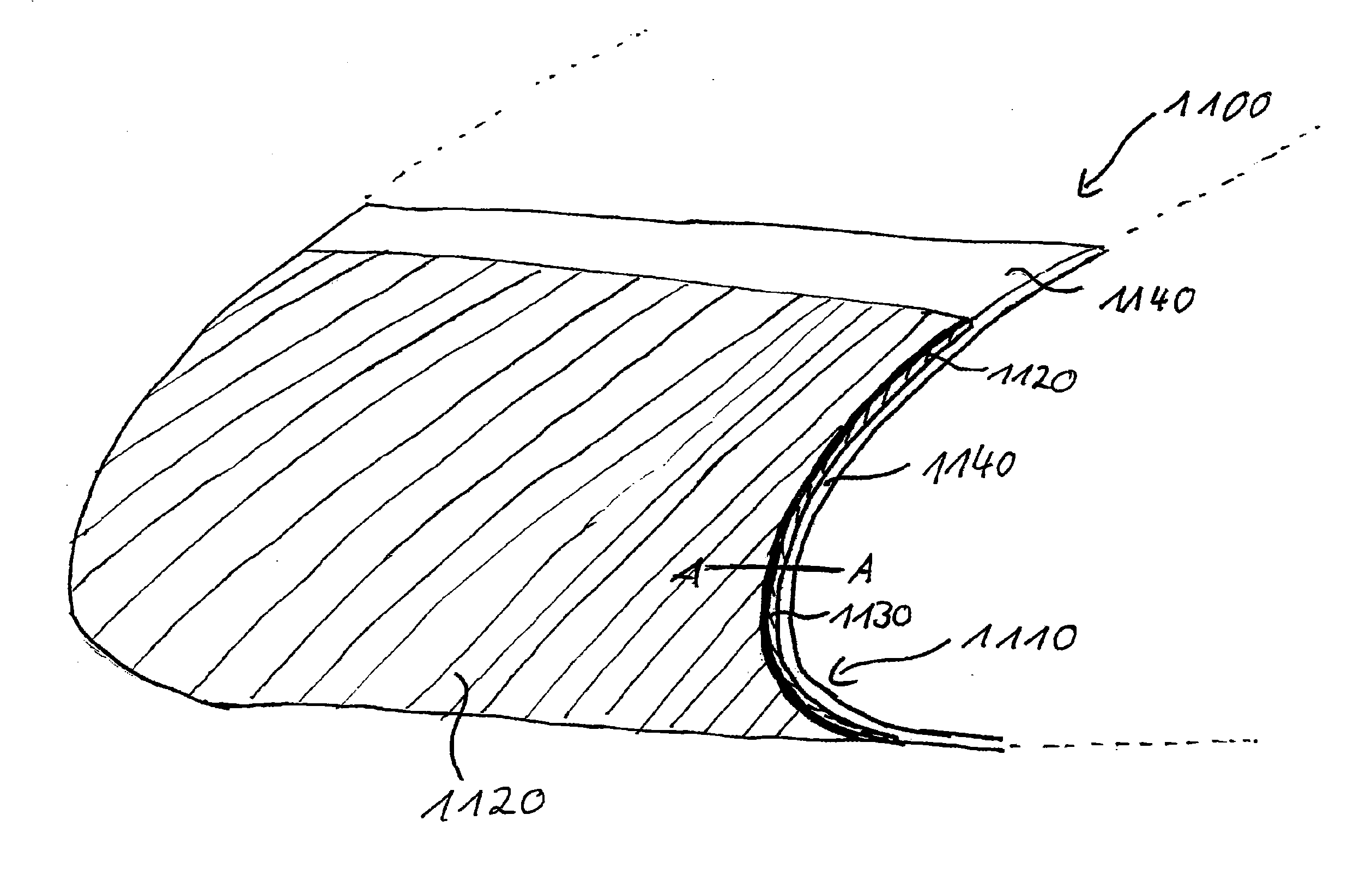
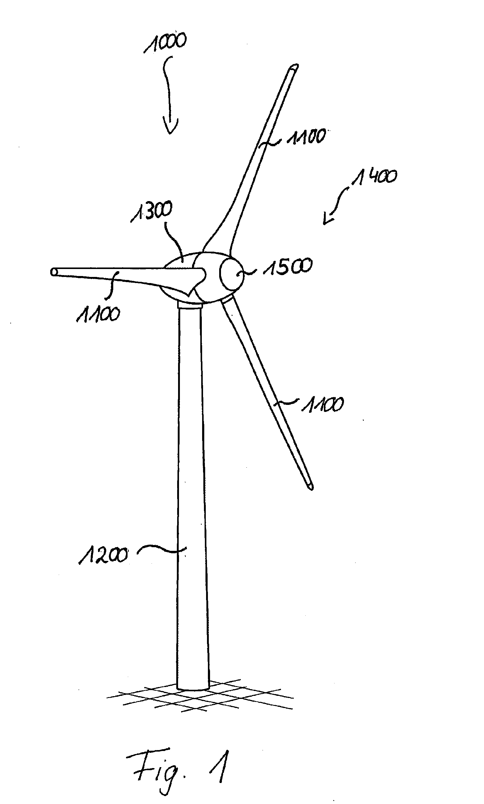
[0043]FIG. 1 shows a wind turbine 1000 with a tower 1200 and with a nacelle 1300. Arranged on the nacelle 1300 there is a rotor 1400 with three rotor blades 1100 and with a spinner 1500. In operation, the wind rotates the rotor 1400, which thus drives a generator in the nacelle 1300. The rotor blades 1100 of the wind turbine 1000 have a base made of fiber material saturated with curable resin and have locally been coated with a surface foil made of UHMWPE, and between the surface foil and the base there is a bonding layer which in turn comprises a first and a second rubber layer. The degree of vulcanization of the first rubber layer here is different from that of the second rubber layer. This structure is illustrated in more detail with reference to the following figures.

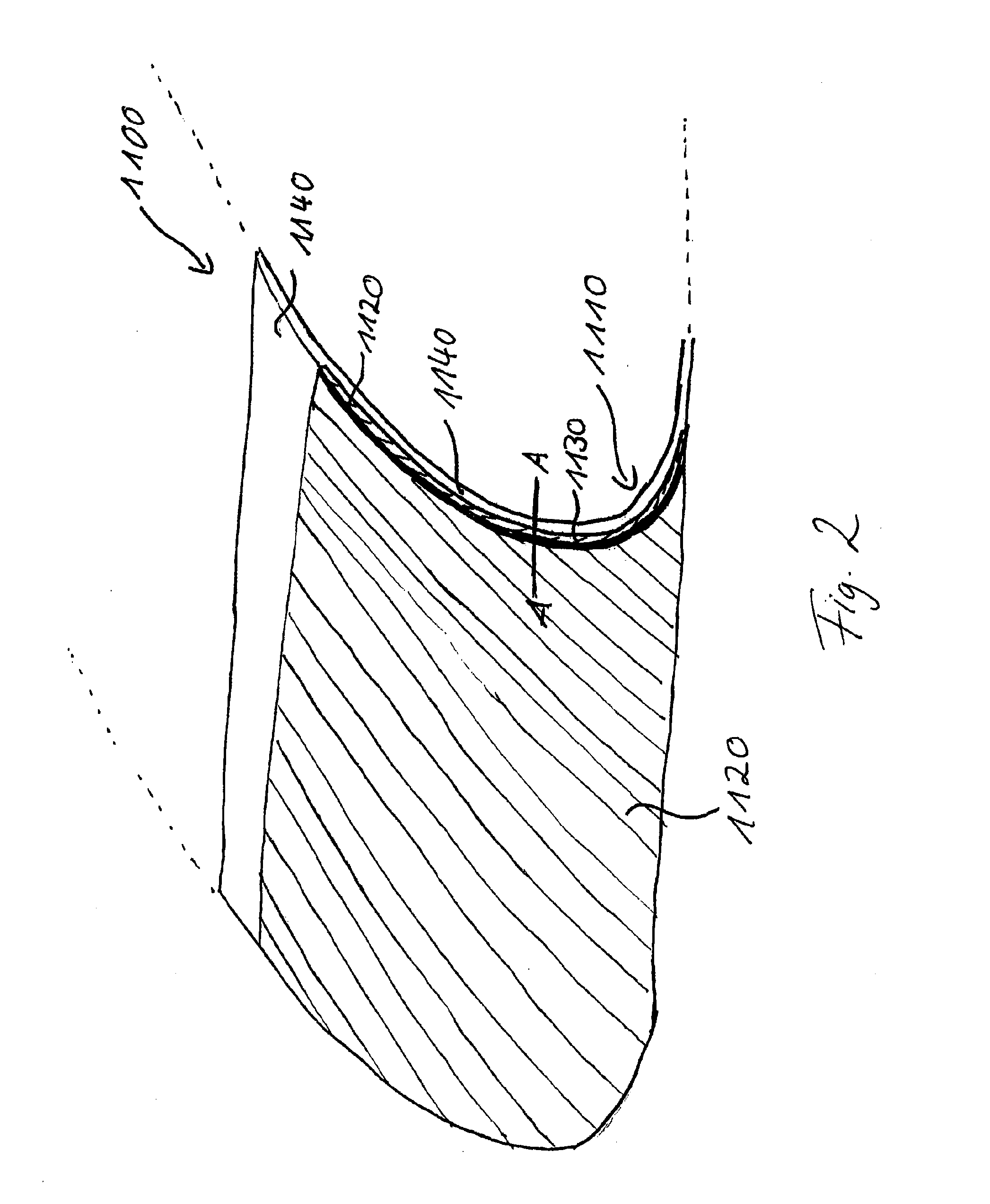
[0044]FIG. 2 shows a rotor blade element 1110 of the rotor blade 1100, namely the leading rotor blade edge. The leading rotor blade edge 1110 has a surface foil 1120. In this embodiment the said foil is composed of ...


PUM

PropertyMeasurementUnit
velocitiesaaaaaaaaaa
pressuresaaaaaaaaaa
temperaturesaaaaaaaaaa

Abstract

A rotor blade element, in particular produced by a process according to claim 10, in particular a rotor blade edge for a wind turbine, with a base comprising a fiber material saturated with curable resin and with a surface foil, with, arranged between base and surface foil, a bonding layer. The invention proposes that the surface foil comprises polyethylene with ultra-high molecular weight and that the bonding layer comprises a first rubber layer and a second rubber layer, where the first rubber layer is allocated to the surface foil and the second rubber layer is allocated to the base.

Description

BACKGROUND[0001]1. Technical Field[0002]The present invention relates to a rotor blade element for a wind turbine, a rotor blade, and a production process for the rotor blade element or the rotor blade. The invention further relates to a wind turbine.[0003]2. Description of the Related Art[0004]Rotor blades for wind turbines have been known for a long time and are described by way of example in DE 10 2004 007 487 A1 and DE 103 19 246 A1. During operation they are exposed to wind pressure, erosion, temperature variations, UV irradiation and high loads due to precipitation. With blade tip velocities up to 300 km / h, sand grains, salt particles, insects or other objects carried by the air have an abrasive effect. This wears the surface of rotor blades, in particular in the frontal edge region. At these locations there is ablation of the rotor surface and therefore a loss of aerodynamic properties and stability.[0005]However, at the same time the rotor blades are intended to have minimum...

Claims


Application Information

Patent Timeline
Patent Type & Authority Applications(United States)
IPC IPC(8): F03D1/06B32B37/18B32B25/14B32B27/32B32B25/08B32B25/04
CPCF03D1/0675B32B25/08B32B25/042B32B25/14B32B2262/101B32B37/182B32B2250/24B32B2603/00B32B27/32B32B25/10B32B25/16B32B2260/021B32B2260/048B32B2307/554B32B2307/558B32B2307/714B32B2307/734Y02E10/72Y02P70/50F03D1/065
Inventor THEILE, BENJAMINHOFFMANN, ALEXANDER
Owner WOBBEN PROPERTIES GMBH
Why Eureka
Try Eureka