Radio-frequency power amplifiers driven by boost converter

a technology of power amplifier and boost converter, which is applied in the direction of amplifier combination, high frequency amplifier, transmission, etc., and can solve the problem of low loss

Active Publication Date: 2016-08-18
SKYWORKS SOLUTIONS INC
View PDF8 Cites 34 Cited by
  • Summary
  • Abstract
  • Description
  • Claims
  • Application Information

AI Technical Summary

Benefits of technology

[0071]For purposes of summarizing the disclosure, certain aspects, advantages and novel features of the inventions have been described herein. It is to be understood that not necessarily all such advantages may be achieved in accordance with any particular embodiment of the invention. Thus, the invention may be embodied or carried out in a manner that achieves or optimizes one advantage or group of advantages as taught herein without necessarily achieving other advantages as may be taught or suggested herein.

Problems solved by technology

The APT mode can result in a lower loss than another die having similar band handling capability but in which the PAs are operated in low voltage.

Method used


Image

  • Radio-frequency power amplifiers driven by boost converter
  • Radio-frequency power amplifiers driven by boost converter
  • Radio-frequency power amplifiers driven by boost converter

Examples


Embodiment Construction

[0098]The headings provided herein, if any, are for convenience only and do not necessarily affect the scope or meaning of the claimed invention.

Introduction:

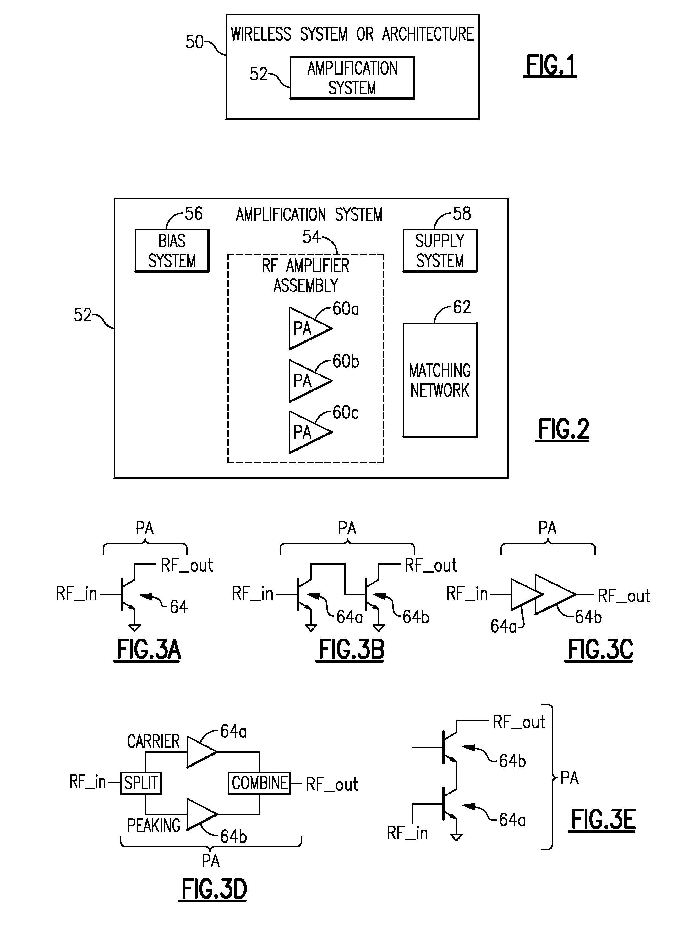
[0099]Referring to FIG. 1, one or more features of the present disclosure generally relate to a wireless system or architecture 50 having an amplification system 52. In some embodiments, the amplification system 52 can be implemented as one or more devices, and such device(s) can be utilized in the wireless system / architecture 50. In some embodiments, the wireless system / architecture 50 can be implemented in, for example, a portable wireless device. Examples of such a wireless device are described herein.

[0100]FIG. 2 shows that the amplification system 52 of FIG. 1 can include a radio-frequency (RF) amplifier assembly 54 having one or more power amplifiers (PAs). In the example of FIG. 2, three PAs 60a-60c are depicted as forming the RF amplifier assembly 54. It will be understood that other numbers of PA(s) can also be impleme...


PUM


Abstract

Radio-frequency (RF) power amplifiers driven by boost converter. In some embodiments, a power amplification system can include a supply system configured to provide a high-voltage (HV) supply signal based on a battery voltage, and a power amplifier (PA) configured to receive the HV supply signal and amplify an RF signal. The power amplification system can further include an output path configured to route the amplified RF signal to a filter. Such an output path can be substantially free of either or both of an impedance transformation circuit and a band selection switch.

Description

CROSS-REFERENCE TO RELATED APPLICATION(S)[0001]This application claims priority to U.S. Provisional Application No. 62 / 116,452 filed Feb. 15, 2015, entitled RADIO-FREQUENCY POWER AMPLIFIERS DRIVEN BY BOOST CONVERTER, the disclosure of which is hereby expressly incorporated by reference herein in its entirety.BACKGROUND[0002]1. Field[0003]The present disclosure generally relates to power amplifiers for radio-frequency (RF) applications.[0004]2. Description of the Related Art[0005]In radio-frequency (RF) applications, an RF signal to be transmitted is typically generated by a transceiver. Such an RF signal can then be amplified by a power amplifier (PA), and the amplified RF signal can be routed to an antenna for transmission.SUMMARY[0006]In some implementations, the present disclosure relates to a power amplification system that includes a supply system configured to provide a high-voltage (HV) supply signal based on a battery voltage, and a power amplifier (PA) configured to receive...

Claims


Application Information

Patent Timeline
Patent Type & Authority Applications(United States)
IPC IPC(8): H03F1/56H03F3/21H04B1/40H03F3/19
CPCH03F1/565H03F3/19H03F3/211H04B2001/0408H03F2200/451H03F2203/21106H04B1/40H03F1/0227H03F1/0266H03F1/0288H03F1/22H03F3/245H03F3/68H03F2200/111H03F3/24
Inventor LEHTOLA, PHILIP JOHN
Owner SKYWORKS SOLUTIONS INC
Why Eureka
Try Eureka