
Method for Manufacturing Composite Ceramic Material

a composite ceramic and manufacturing method technology, applied in the field of composite ceramic materials, can solve problems such as deterioration of stack performance, and achieve the effect of excellent electrical conductivity

Inactive Publication Date: 2016-11-10
POHANG IRON & STEEL CO LTD
View PDF2 Cites 3 Cited by
  • Summary
  • Abstract
  • Description
  • Claims
  • Application Information

AI Technical Summary

Benefits of technology

The present invention is about creating a material that improves the electrical connection between two components of a fuel cell in an oxidizing atmosphere, while being chemically and mechanically stable. This material has excellent electrical conductivity and maintains a stable state during operation. This patent is also about the method for making this composite ceramic material.

Problems solved by technology

In the case of the solid oxide fuel cell, since electrical energy generated by one unit cell has a limitation, generally, a stack structure where a plurality of unit cells is laminated is formed.
However, in the case where the metal material is used as the current collector, when the material is exposed to an oxidizing atmosphere over a long period of time, there is a problem in that oxides are formed on a surface thereof to increase resistance of a stack, thus deteriorating performance of the stack.

Method used


Image

  • Method for Manufacturing Composite Ceramic Material
  • Method for Manufacturing Composite Ceramic Material
  • Method for Manufacturing Composite Ceramic Material

Examples


example 1

[0073]First, lanthanum cobaltite was synthesized as one of starting materials.

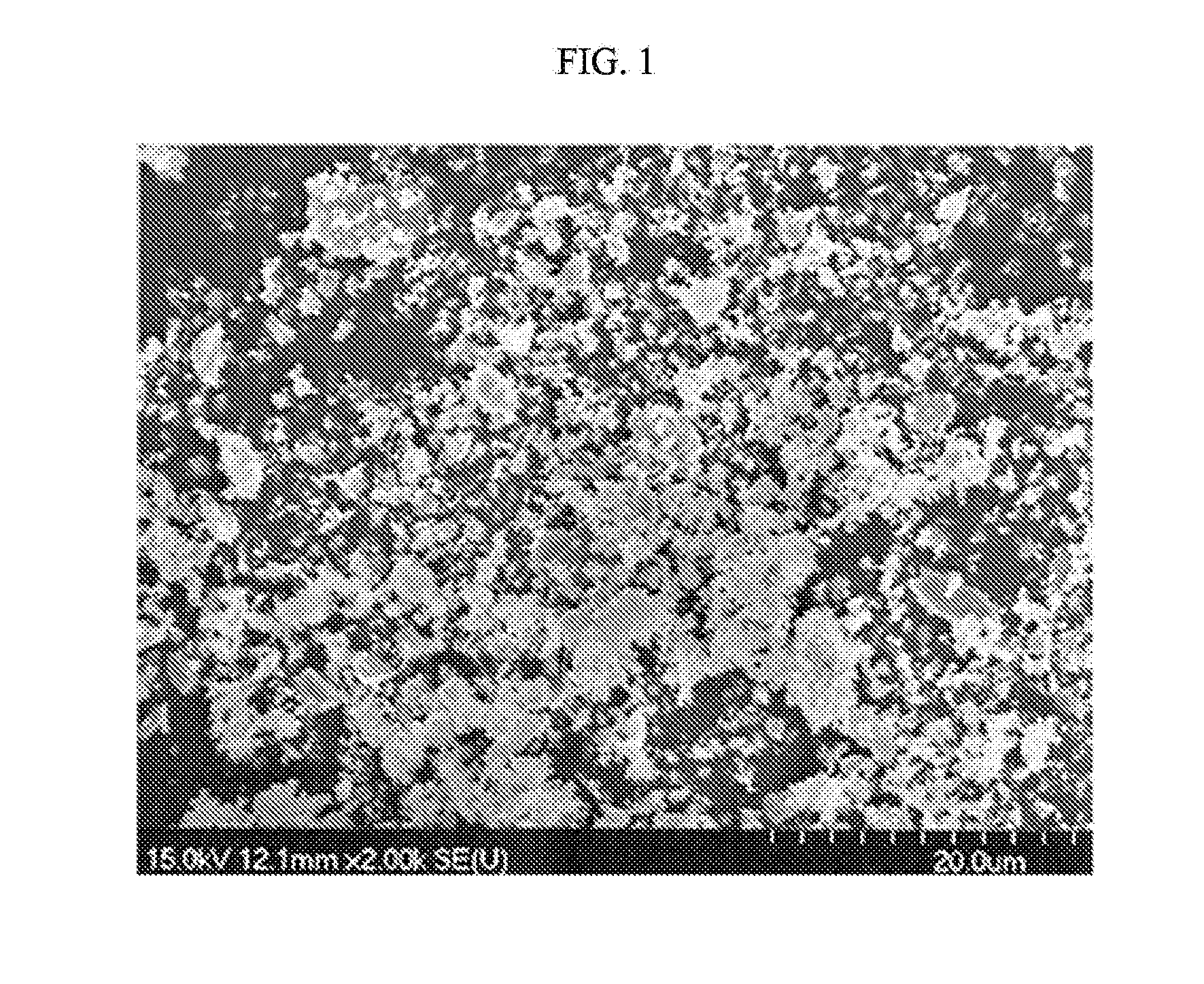
[0074]To this end, lanthanum oxide and cobalt oxide were mixed, and heated at the temperature of 1400° C. for 5 hours or more to synthesize lanthanum cobaltite. The synthesized lanthanum cobaltite was pulverized to form a powder state. The manufactured powder of lanthanum cobaltite was manufactured to have a dense and spherical shape without pores between primary particles as shown in the picture taken by the scanning electron microscope (SEM) of FIG. 1. The average particle diameter of the manufactured lanthanum cobaltite was about 3 μm.

[0075]Next, the nitrate aqueous solution was manufactured. The composition of the nitrate aqueous solution was adjusted by weighing and mixing nitrates so that the composition of the finally formed perovskite ceramic was (La,Ca) (Cr,Co,Cu)O3 (hereinafter, referred to as ‘LCCAF’). The accurate composition of LCCAF used in the present Example was (La 0.8Ca0.2)(Cr0.1Co0.6Cu0....

example 2

[0089]In Example 2, the amount of synthetic powder manufactured according to Example 1 was increased to be 250 g in one batch, and physical properties with pure LCCAF powder were compared. (The amount of synthetic powder synthesized in Example 1 is 100 g in one batch.)

[0090]First, pure LCCAF powder was synthesized by adding only the citric acid to the nitrate aqueous solution weighed in a stoichiometric composition. In addition, synthetic powder was synthesized by the same method as Example 1 for the purpose of comparison therewith. In this case, the composition of lanthanum cobaltite in synthetic powder was set so that the ratio of lanthanum cobaltite in powder obtained after calcining was 50 wt % . Hereinafter, synthesized LCCAF powder is called “pure LCCAF powder”, and synthetic powder synthesized for comparison is called “50% synthetic powder”.

[0091]The powders synthesized as described above were shaped into disks having the diameter of 25 mm by each adding 1.0 wt % of polyvinyl...

example 3

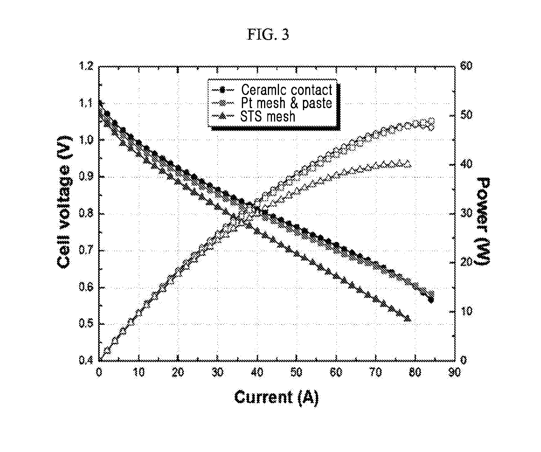
[0094]In Example 3, synthetic powder manufactured according to Example 2 was applied as a contact material to the separation plate of the solid oxide fuel cell, and electric characteristics of the fuel cell were examined.

[0095]The sample used in this experiment is 50% synthetic powder synthesized according to Example 2.

[0096]Synthesized 50% synthetic powder, the organic combining material, the dispersion material and the solvent were mixed with each other to manufacture the slurry.

[0097]This slurry was put into the syringe-shaped container, and applied in a linear form on the solid oxide fuel cell separation plate by using a dispenser device. Further, this was sintered in the air at 850° C. for 4 hours.

[0098]In the used solid oxide fuel cell, the single cell was formed of LaSrCoFeO3 (LSCF) anode, yttria stabilized zirconia (YSZ), and Ni—YSZ cathode, the separation plate was formed of a stainless steel material (ferritic steel), and the sealing material was glass.

[0099]In this case, ...


PUM

PropertyMeasurementUnit
particle diameteraaaaaaaaaa

Abstract

Provided is a method of making a composite ceramic material for a fuel cell. The composite ceramic material for the fuel cell forms a cored structure where perovskite ceramic particles having a small particle diameter surround lanthanum cobaltite particles having a large particle diameter. Lanthanum cobaltite is added as a starting material in a process of synthesizing the perovskite ceramic particles. The composite ceramic material for the fuel cell made according to this method improves an electric connection characteristic between a separation plate and a polar plate of the fuel cell, and is chemically and mechanically stable.

Description

CROSS-REFERENCE TO RELATED APPLICATION[0001]This application is a divisional of, and claims priority to, U.S. patent application Ser. No. 13 / 519,699, filed on Dec. 28, 2010, which claims priority to Korean Patent Application No. 10-2009-0131639, filed on Dec. 28, 2009, the disclosures of which are hereby incorporated by reference.BACKGROUND OF THE INVENTION[0002](a) Field of the Invention[0003]The present invention relates to a fuel cell, and more particularly, to a composite ceramic material electrically connecting an anode and a separation plate of a fuel cell, and a method for manufacturing the same.[0004](b) Description of the Related Art[0005]Among fuel cells, if a solid oxide fuel cell (SOFC) is described as an example thereof, the fuel cell is formed of a structure where a plurality of electric generating units formed of a unit cell and a separation plate are laminated.[0006]The unit cell includes an electrolyte film, an anode (air electrode) disposed on one surface of the el...

Claims


Application Information

Patent Timeline
Patent Type & Authority Applications(United States)
IPC IPC(8): H01M8/0217C04B35/624C04B35/64C04B35/50
CPCH01M8/0217C04B35/50H01M2008/1293C04B35/64C04B2235/3275C04B35/624B82Y30/00C01G45/12C01G51/006C01G51/70C01G53/006C01G53/70C01P2002/34C01P2004/03C01P2004/61C01P2004/62C01P2004/82C01P2004/84C01P2006/40C04B35/01C04B35/62685C04B35/62805C04B35/62826C04B35/62892C04B2235/3208C04B2235/3227C04B2235/3241C04B2235/3281C04B2235/443C04B2235/449C04B2235/528C04B2235/5436C04B2235/5454C04B2235/768C04B2235/9615H01M4/8657H01M4/9033H01M8/0236Y02E60/50Y02P70/50
Inventor HAN, SANG-MOOKIM, DO-HYEONGJUN, JOONG-HWAN
Owner POHANG IRON & STEEL CO LTD
Learn More